The Monkeybrain went micro

Shortly after finishing the first Monkeybrain prototype I was reminded that my piloting skills still aren’t up to par and I needed something smaller and easier to fix.

…just a tiny bit more practice.

So I shrunk the board as much as I could while still keeping to two copper layers and added four FETs to drive brushed micro motors. Dimensions are 25 * 40 mm.

The botchwires on the left are where the video OpAmp would have been if I had managed to get it working.

I bought a micro H frame on eBay and slapped the board on there, along with a camera, video transmitter and a knock off Spektrum satellite receiver.

Maintenance shot: The antenna is pretty beat up by now, but the wire it’s made from is way too soft for the purpose. Also, the SW prop needs replacing (all of them, really, but these are a bit pricey and I am cheap, so they stay until they are ripped to shreds).

Although it does fly, it is still quite heavy, even after switching the hardware over to nylon. The only things left to strip down that I can think of now are the vTX’s shield and the FC’s PCB.

The next revision is only .8mm and weighs in at 1.9g while the Oshpark boards were 3.4g unpopulated.

Posted in Analog, ARM, Digital, PCB, RC | Comments Off on The Monkeybrain went micro

Meet the Monkeybrain Flight Controller!

Anybody who’s ever bought a flight controller before knows that there is quite a bit of choice overload. The prices range from ten to several hundred Euros, and what that gets you goes from an Arduino with an MPU6050 to STM32F4 boards with all bells and whistles.

The one that impressed me the most was the BrainFPV, with integrated OSD (on screen display) for FPV (first person view) flying. But those weren’t available anywhere, so I had to make my own.

The I2C pull-ups are missing in this design. An earlier version of the board had them, but I somehow managed to delete them from the schematics without even noticing.

As I’ve never seen one of the original BrainFPV boards up close, a lot of guesswork was involved in reverse engineering the circuit. I’ve left out a few parts, which slightly degrades the video quality in my first prototype. This and the fact, that my board is merely a re-design of another board, led me to call my creation the Monkeybrain.

I don’t have a way to put silkscreen on my homemade boards, so I abuse the soldermask layer for that.

It’s no accident that the board looks like an RCExplorer Tricopter frame, because it’s meant as a drop in replacement for the Tricopter I built earlier.

Posted in Analog, Digital, Manufacturing, PCB, RC | Comments Off on Meet the Monkeybrain Flight Controller!

Moved my blog.

I’ve lost some of my domains and also the pictures on my old blog, so I decided to start over and move the blog to a new place.

This means that any old addresses of this blog will no longer work. These include but are not limited to:

– blog.arles-electrique.de
– testblog.arles-electrique.de
– blog.aletux.de
– testblog.aletux.de

Posted in Uncategorized | Comments Off on Moved my blog.

I’ve built a copper plating station

As I was designing more and more circuit boards, I got increasingly annoyed with waiting up to 8 weeks for a batch of boards. Also, ever so often I noticed errors in the layout after sending it away for manufacture. So I started acquiring the tools and skills to make my own boards.

Here’s a cross section of a 0.3mm hole.

Initial tests with toner transfer were promising, but showed that the toner transfer process was very sensitive to dirt and dust, of which there’s plenty in my lab. So I quickly  moved on to photoimaging the layouts, which worked a lot better in my dirty environment (especially after I discovered an extremely simple wet lamination process).

This is a tiny test board with 1.0, 0.8, 0.7, 0.4 and 0.3mm holes, in rows of two. The board is 1.6mm thick, BTW.

With the ability to image, develop and etch boards with feature sizes down to 4/4mil (when using actual laser exposed film, 5/5mil with laser printed transparencies), the only missing link was a way to plate through holes and vias.

Another test board, etched and tinned. The .8 and 1mm holes are all off center due to a CNC mishap, but all the other holes are successfully plated through.

So I designed a cheap and easy to build copper plating station. The full project log is over at hackaday.io. There is even a short video. Check it out:

Posted in CAD, Chemistry, Manufacturing, PCB | 3 Comments

DIY UV Exposure Lamp

Those are 7, 6, 5, and 4 mil traces from top to bottom.

I’ve made a UV exposure unit out of a cheap curing lamp for fake fingernails. Check out the Instructable I wrote!


Posted in CAD, Chemistry, Manufacturing, PCB | Comments Off on DIY UV Exposure Lamp

Cheerson CX-10 Mod done properly this time around

I accidentally did the coolest paint job. I wanted to spray paint a CX-10 shell and rubbed it with nail polish remover to clean it. It dissolved a bit of the original paint, but that didn’t bother me too much. I also gave the spray can only a very brief shake, not the minutes you’re supposed to. Next thing I know, it looked like this:

It’s got something alien skin like or something.

I also went ahead and removed the switch and added the tape like I said I wasn’t going to. I even cut open a new lower shell, but this time I left the bottom in place, which also got a few layers of tape for added stability.

You can still see the piece of wire bridging the switch terminals.

Posted in RC, Toy Hacks | 3 Comments

Cheerson CX-10 Battery Mod

The Cheerson CX-10 is an amazing little Quadcopter that can be had for as little as 15 Euros at your favourite chinese retailer. It’s tiny and a ton of fun to fly (with a proper TX, that is). But there is one thing I don’t like about it, and that is the battery being permanently mounted inside. What makes matters worse is that the included charger charges the battery too fast, which decreases battery life. Long story short, what I came up with was this:

Maybe a piece of Kapton tape wouldn’t hurt here…

The batteries (these, IIRC) I ordered came with plugs that fit the charging connector on the quad. Nice. So all there is to do is remove the built in battery and bridge the switch as in the picture. In case it’s hard to see: It’s the outermost pads that need to be bridged, but it doesn’t hurt if you bridge all three terminals. Of course you could remove the switch, but I didn’t bother. Maybe I’ll do it when I have to replace the next motor.

The replacement battery fits nicely.

Now I can charge my batteries at a rate that won’t kill them after ten cycles and swap them out like on a “real” Quadcopter.

The rubber band adds a bit of DIY charme to it.

I had to add a picture with my Devo, just because the two of them look so nice together.

There is no banana in this picture.

Update: I actually went and did this one properly later that day..

Posted in RC, Toy Hacks | 24 Comments

Devo 8s Multimodule mount

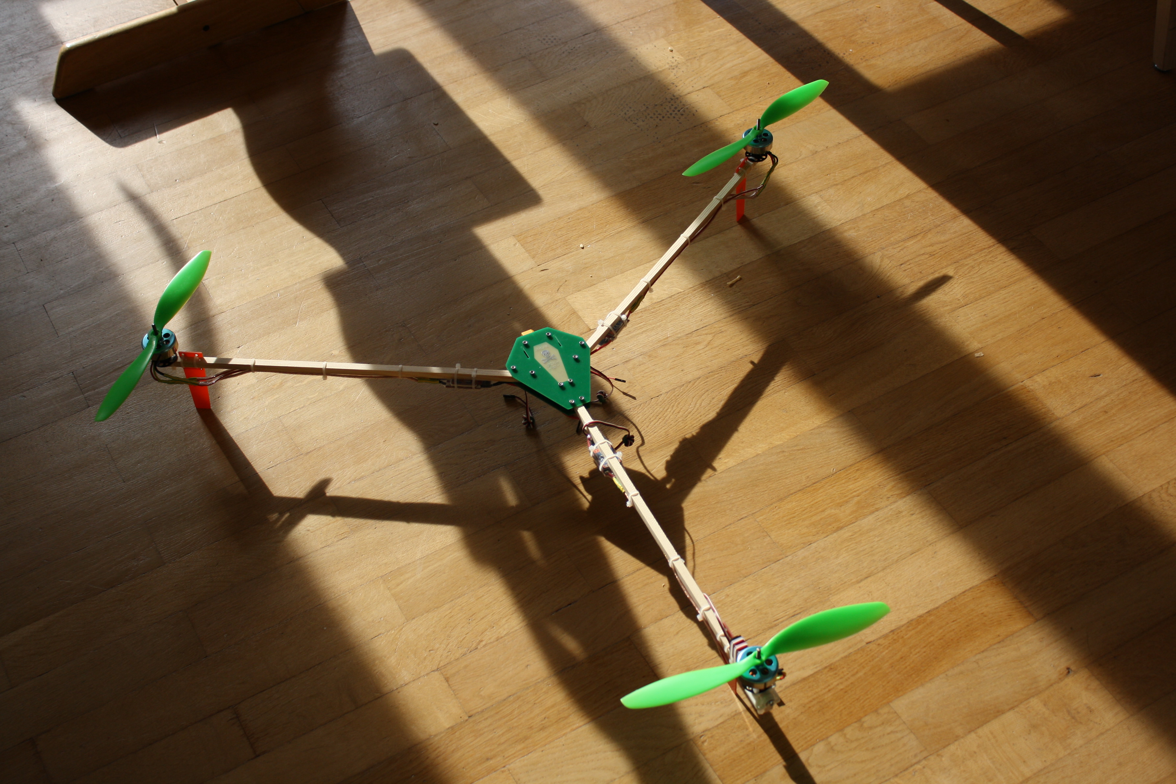
I have a Devo 8s RC transmitter which I adore. What I love most about it, is that there is Deviation, a great open source firmware project for it, which enables you to add transceiver modules for it and (at least in theory) speak virtually any protocol out there.

There is one slight little inconvenience though. The maximum of modules you can add at this time is three (actually it’s only two but there is a way around that), which makes for a total of four. Which means, you have to have four antennas somewhere. Which in turn drove me into learning how to use 3D CAD software (which is a totally awsome experience, btw).

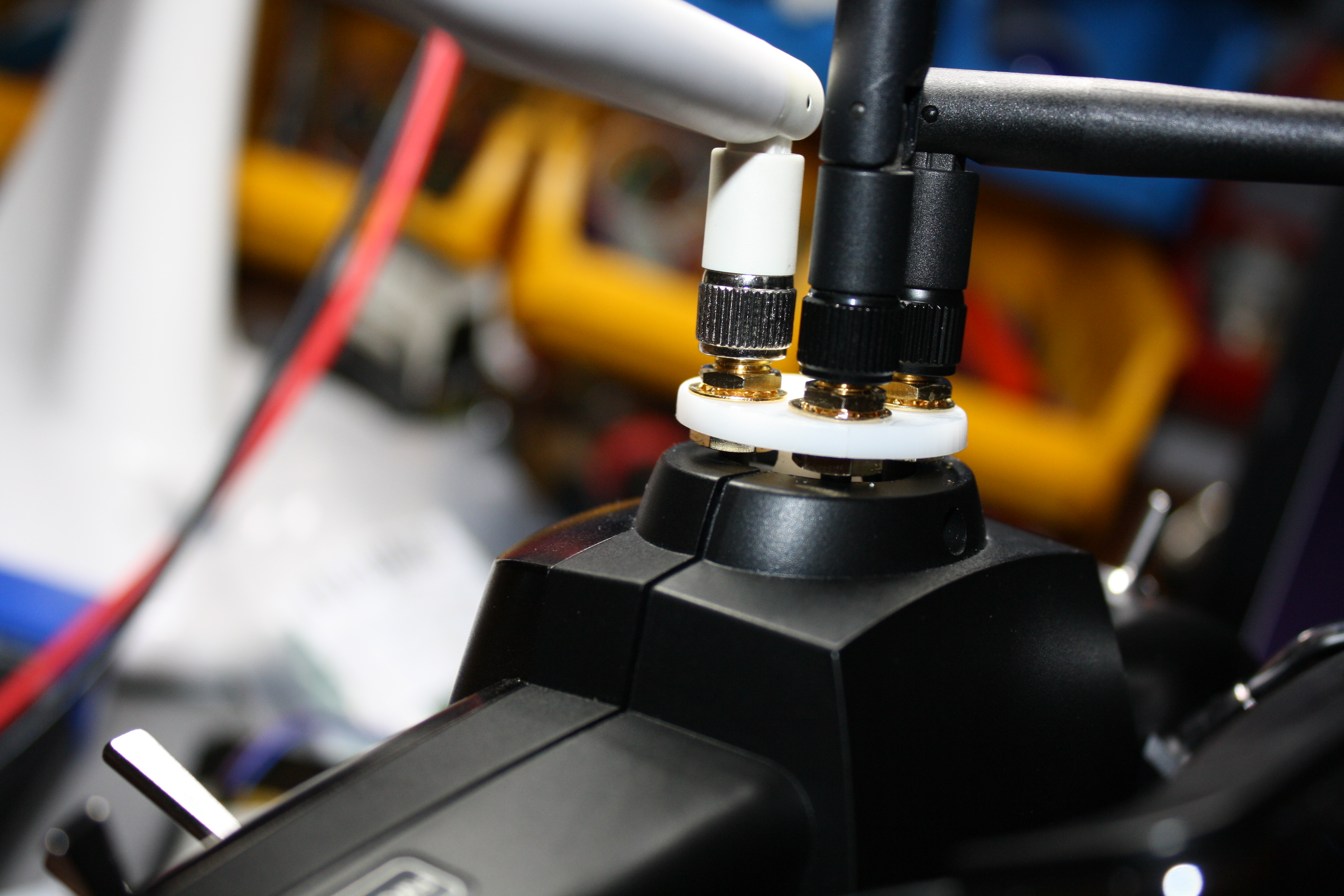
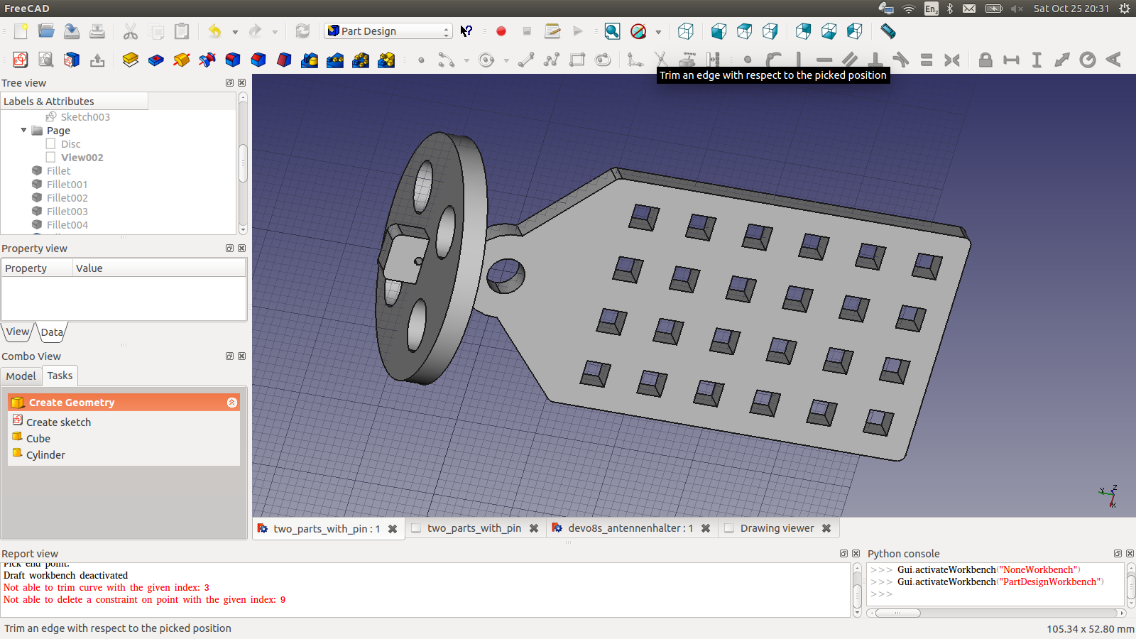
What I tried to do was create a reversible way to mount those four antennas as well as the quite chunky Multimodule itself (although I didn’t think of that until later, of course). If you remove the stock antenna mount, you are left with a 20mm diameter hole with a 4.6mm rod going through in the middle. So I came up with a disc a little wider than the hole to mount the antennas on, and a little clamp that would be used to anchor it on the rod. The whole thing was intended to be laser cut out of 3mm acrylic with two clamps back to back for added stability.

The very first incarnation still without the module mount.

It actually kind of worked but I still hadn’t figured out how to mount the module yet. I wanted some kind of mounting plate with holes in it so I could just ziptie the Multimodule to it. So what I came up with was this:

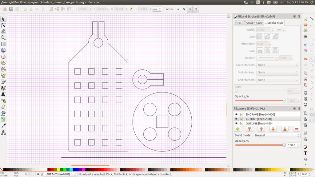
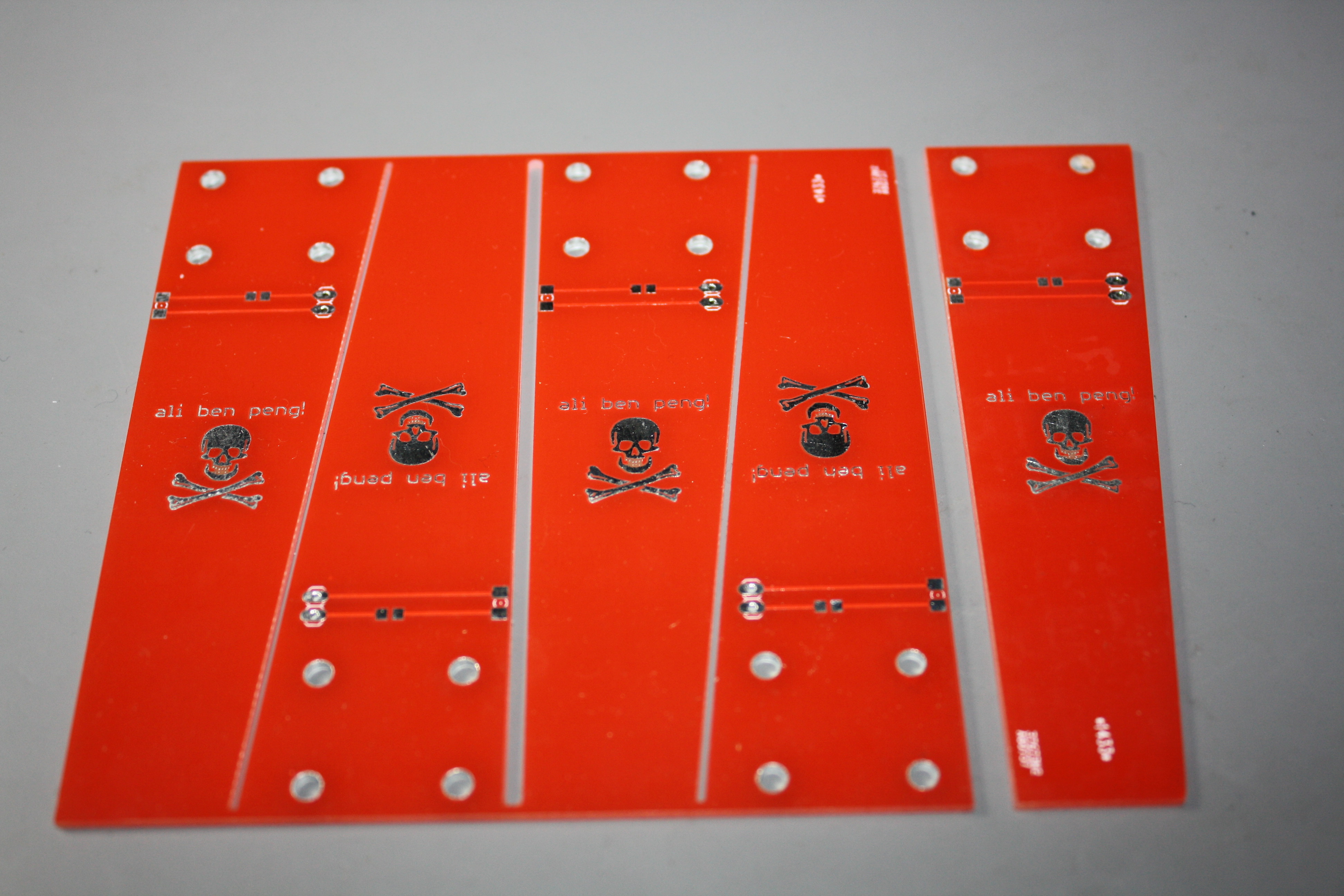
These are the 2D exported parts in Inkscape for the first version with the module mount.

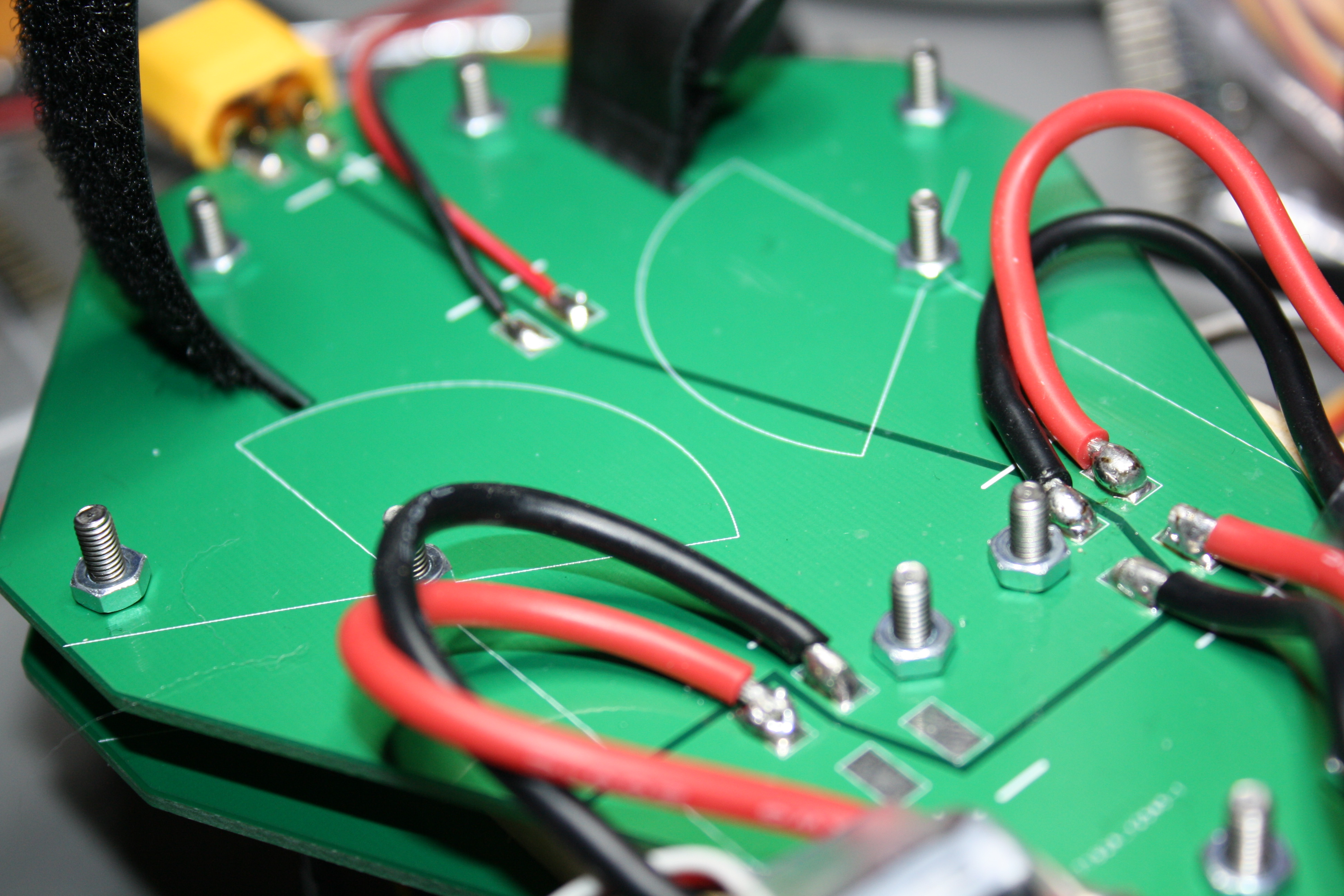
This is the version I am using right now and so far it works great.

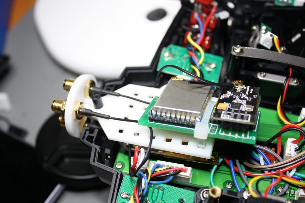
Mounting the Multimodule with a ziptie worked out pretty neat.

I didn’t mount the fourth antenna yet because the A7105 module came with a piece of wire instead of a U.FL connector. But then, anything I would fly with that particular module, I wouldn’t fly very far anyway, so I didn’t bother to either order and wait for a connector to put on there or just botch a cable on there.

Originally the whole contraption was meant to be press fit, but I soon realized that was never going to happen. Not with the laser cutter at our hackerspace and my patience, at least. So a liberal amount of high viscosity superglue did the trick instead.

The gap between the enclosure and the antenna mount is intentional. The nuts on the SMA connectors wouldn’t fit inside.

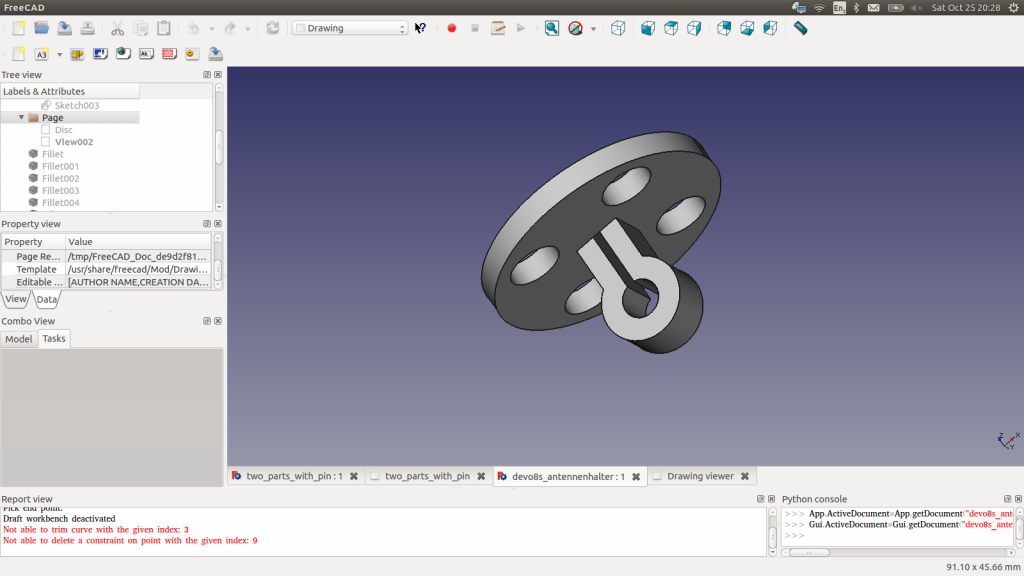
I was still a bit worried about stability, as there is no anchor for the antenna mount on the outside, so I altered the design another time and came up with this:

The very last incarnation. Untested so far.

On this one there are only two parts instead of three and the module plate protrudes from the antenna mount. It also has a little hole to put a tiny steel rod through, instead of the slit that didn’t really work out. That and (again) a generous squeeze on the superglue bottle should make up in stability for the reduced thickness of the joint.

I haven’t built that one yet and I just never might, because the current prototype works for me, but maybe somebody else will. Here are the files.

Posted in 2.4GHz, CAD, RC | Comments Off on Devo 8s Multimodule mount

RCExplorer Tricopter v2.5 Build

Over the last year or so I’ve picked up flying RC multicopters. I started out with micro and nano sized toy quads like the Hubsan X4, which are great for learning the basics about flying such a thing, but eventually I wanted something more “Hobby grade”. Something I will have to build myself. Something “real”. Also something intimidatingly large, as it turned out.
I used the original arm length of 48cm and the thing is humongous! Those are 11″ props on there (not screwed on of course, just for scale). And please excuse the unit confusion. We have the metric system where I live, but some things like screen sizes or propeller diameters are commonly measured in inches.

So I decided to build a Tricopter design conceived by RCExplorer’s David Windestål, v2.5.

My take on David’s “Coffin Body”

Frame and Landing Gear

David’s original design features an arrow shaped frame, but there is also an alternative version which he called the coffin body, for obvious reasons. That was the frame I wanted to use, but I didn’t know where to buy and/or cut carbon fiber or fiberglass. Except for PCB fab houses, of course, so I went and designed a board in Eagle. While I was at it, I played around a bit and added a power distribution system and a bit of “coffin art in copper, tin and solder mask”. And yes, I know, this would have probably looked a lot cooler with black solder mask, but the boards were expensive enough as is, and I didn’t want to spend another 16 or so Euros for black soldermask before I even know if my concept worked.

The landing gears are also just PCBs designed in eagle. They have footprints for 1206 LEDs and 0805 resistors on them. Oh, and little skulls, of course!

Power distribution

Originally I had planned to put the wiring on the inside of the sandwich, but that didn’t work out due to too short battery leads on the ESCs. And I had a hard time unsoldering the original leads. As a matter of fact, I eventually gave up on it after repeatedly failing to remove the leads even with the whole solder joint liquefied. It felt like they were spot welded or glued on there somehow. Anyway, I was afraid to completely destroy the ESC boards, so the original leads stayed on, end of story. Also, I soldered the battery connector directly to the board because I didn’t have any beefy cable handy at the time, but I’m not sure it’s a good Idea. it looks like it’s just waiting to break off in a crash.


Those solder joints don’t look too good. I should probably redo them before something bad happens.

Also the screws are way too long and I didn’t have lock nuts, but I hope that the generous amount of thread lock I applied after taking the picture will hold everything in place.

Just a cheap Arduino clone. Please move along.

Electronics
I used a Frsky D8-Something RX with PPM output and a Chinese Arduino pro micro knock off running MultiWii with a MPU6050 sensor board, for now. I’m planning on replacing it with a Chinese CC3D knock off later.

From left to right: Servo/ESC interface board, FrSky RX, MPU6050. And yes, I know the wiring looks like shit.

I used a bit of protoboard to interface the Arduino with the ESCs. This might go into a later version of the frame, along with an I2C Bus, to ease playing around with different kinds of sensors. Oh, and a voltage divider wouldn’t hurt either, I guess.

Setup/Test flight

I’ve begun setting up MultiWii, but so far the copter wont behave itself. I suspect the PID values are way off, but I just don’t have the experience to tell exactly what is going on. I’ve even got it off the ground for a few seconds once, but I don’t consider that a successful flight, even though it stayed in one piece, because I couldn’t really control it.

The beast folded up. The original frame design leaves a bit more sp
ace for zip-ties closer to


After the crash…

There’s no point in pretending that I won’t involuntarily destroy this thing rather sooner than later, so I already have a few things planned to do after the first fatal crash:
  • Try again to desolder the original power leads from the ESCs and put custom length leads on them. Don’t chicken out prematurely this time
  • Mount the ESCs as close as possible to the motors
  • Put the power distribution side of the board on the inside of the sandwich.
  • Buy the right length screws and lock nuts for the frame
  • Build the Battery/Camera mount from David’s design
  • Try shorter and maybe thicker arms
  • Put the LEDs and resistors on the landing gears before mounting them to the copter
  • Redesign the frame board to use the original arrow shape and put signal distribution, a voltage divider and an I2C bus on it. Hell, maybe even a few LED drivers if I feel like it! After all there is one completely unused layer of copper on there (unless you count the skull doodle)
  • Something I don’t know yet. Perhaps something dangerously stupid.
Posted in CAD, PCB, RC | Comments Off on RCExplorer Tricopter v2.5 Build

Toellner Lab Bench PSU Repair

For quite some time I wanted a “real” bench power supply. The problem is, the good ones are expensive and the cheap Chinese ones are usually crap. So I bought an old Toellner TOE8433 on Ebay.

According to the seller the left instrument was broken and always on full tilt, the cause being “probably just being a bad solder joint”. That wasn’t it.

The PSU has three outputs: A 3-6V output and two identical 0-30V 0-1A outputs, one of which was broken and put out about 44V, no matter what. The instrument itself, on the other hand, was completely fine. There just wasn’t any scale left.

A first try to repair it without schematics didn’t work out so good. I found a few broken components but I didn’t find the cause of the fault. So I went hunting for schematics on the net, without success. There was one guy selling the schematic I needed but he wanted 10 € for the PDF. That couldn’t be any more than a last resort. So I tried contacting Toellner themselves. I knew that was a long shot, but since I was reluctant to give somebody 10 € for a PDF, I had to give it a try.

I wrote a mail explaining that I bought an out of production PSU on the net, that I was on a tight budget and asking nicely for the schematics. I didn’t really expect an answer at all, but two hours later I had a mail in my inbox, reading something along the lines of “Dear Sir, enclosed you’ll find the files from the years 1984 and 1992. Please recommend us. Best regards…”. Attached were complete schematics, BOM and a description of how the circuit worked (which I didn’t entirely understand, even after reading it ten times – more than three transistors interacting with each other still make my brain hurt).

With the schematic, repairing the thing was a piece of cake. I soon found out that an internal supply voltage was missing and found the fault in the generation of that voltage, so after fixing that, everything worked perfectly again.

The only question remaining is, how did the previous owners manage to break the thing in the first place? These devices are widely in use in educational workshops, so they can take quite a bit of abuse. Shorted outputs and even hooking up voltages shouldn’t be able to damage them. Hooking up mains could do the trick, though, I suppose.

So I want to thank Toellner for supplying me with the schematics, and no, I won’t share them. They have been nice to me and I don’t want to piss them off by publishing their stuff on the net. I value open source a lot, but these files aren’t open source or public domain, and I have to respect that. If you want them, go and ask for yourself.

Posted in Analog | Comments Off on Toellner Lab Bench PSU Repair