 |
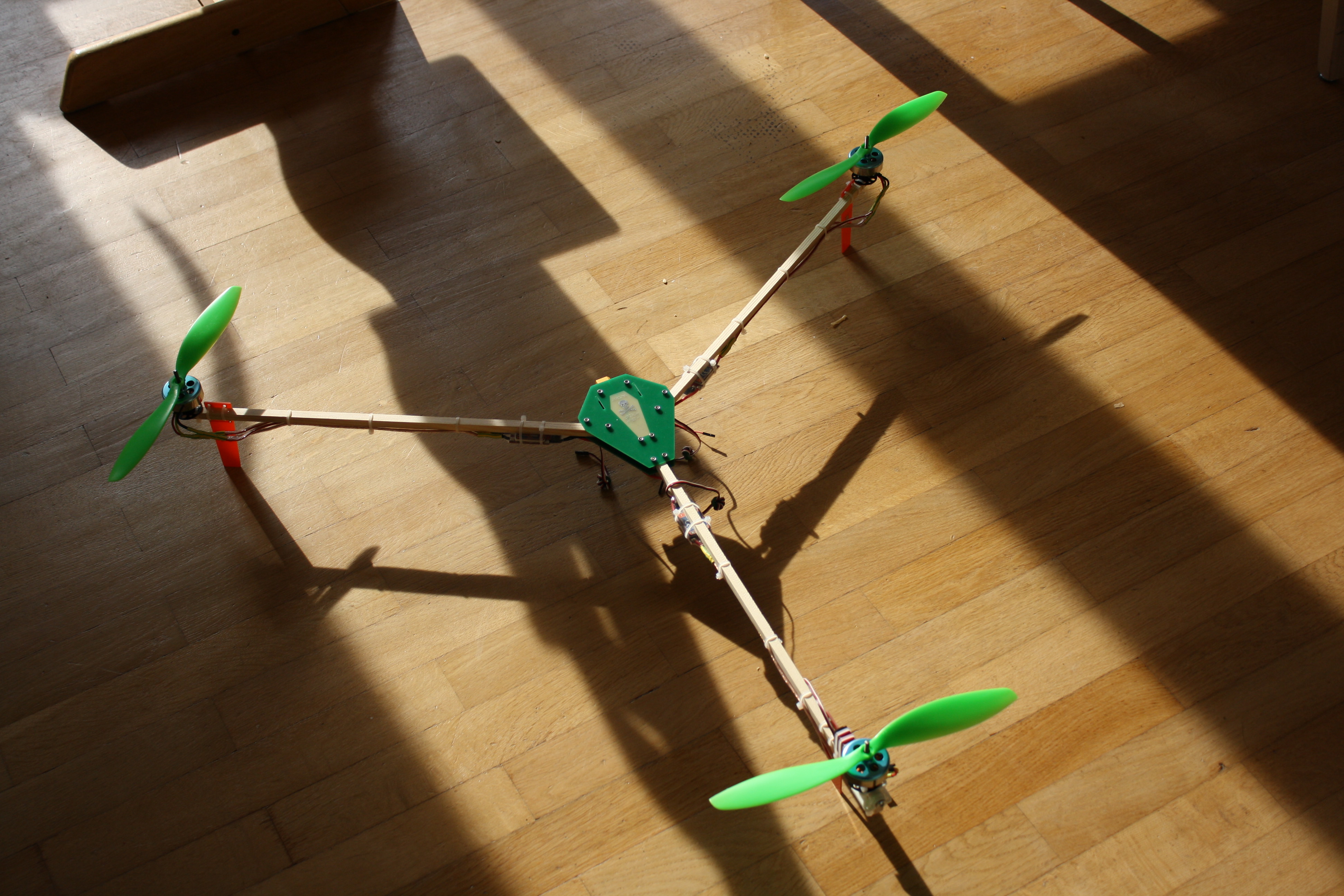
| I used the original arm length of 48cm and the thing is humongous! Those are 11″ props on there (not screwed on of course, just for scale). And please excuse the unit confusion. We have the metric system where I live, but some things like screen sizes or propeller diameters are commonly measured in inches. |
So I decided to build a Tricopter design conceived by RCExplorer’s David Windestål, v2.5.
 |
| My take on David’s “Coffin Body” |
Frame and Landing Gear
David’s original design features an arrow shaped frame, but there is also an alternative version which he called the coffin body, for obvious reasons. That was the frame I wanted to use, but I didn’t know where to buy and/or cut carbon fiber or fiberglass. Except for PCB fab houses, of course, so I went and designed a board in Eagle. While I was at it, I played around a bit and added a power distribution system and a bit of “coffin art in copper, tin and solder mask”. And yes, I know, this would have probably looked a lot cooler with black solder mask, but the boards were expensive enough as is, and I didn’t want to spend another 16 or so Euros for black soldermask before I even know if my concept worked.
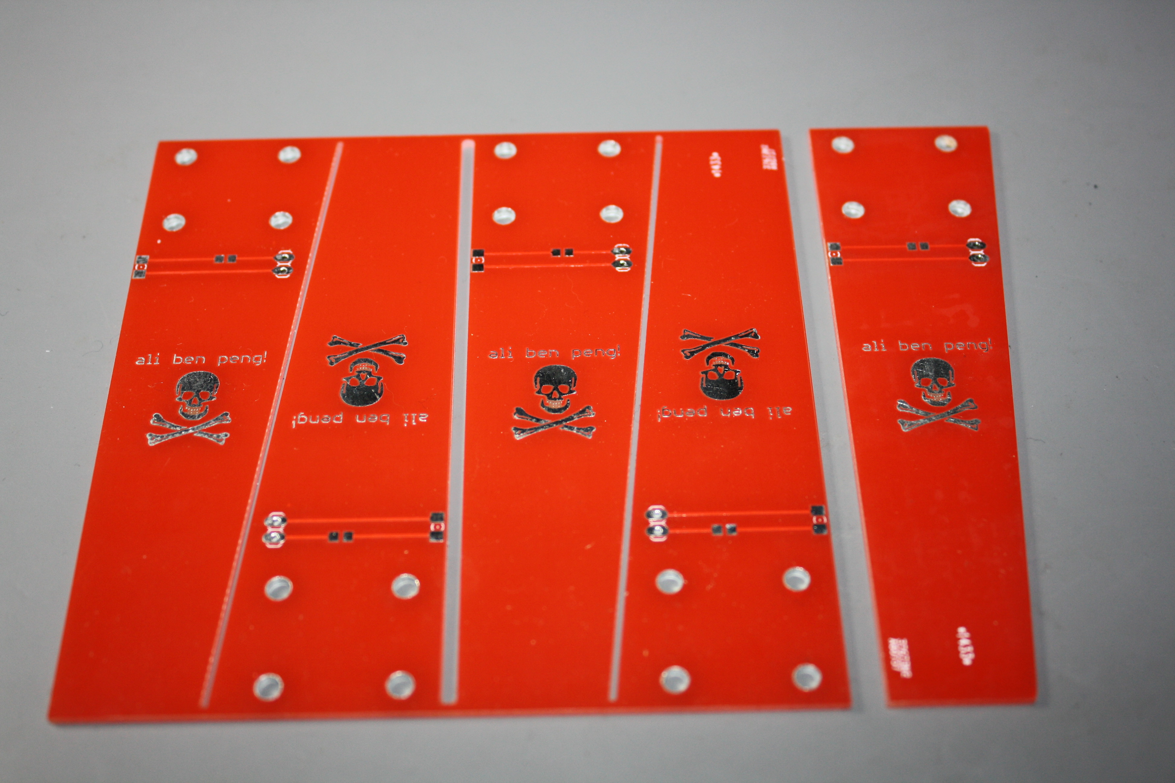 |
| The landing gears are also just PCBs designed in eagle. They have footprints for 1206 LEDs and 0805 resistors on them. Oh, and little skulls, of course! |
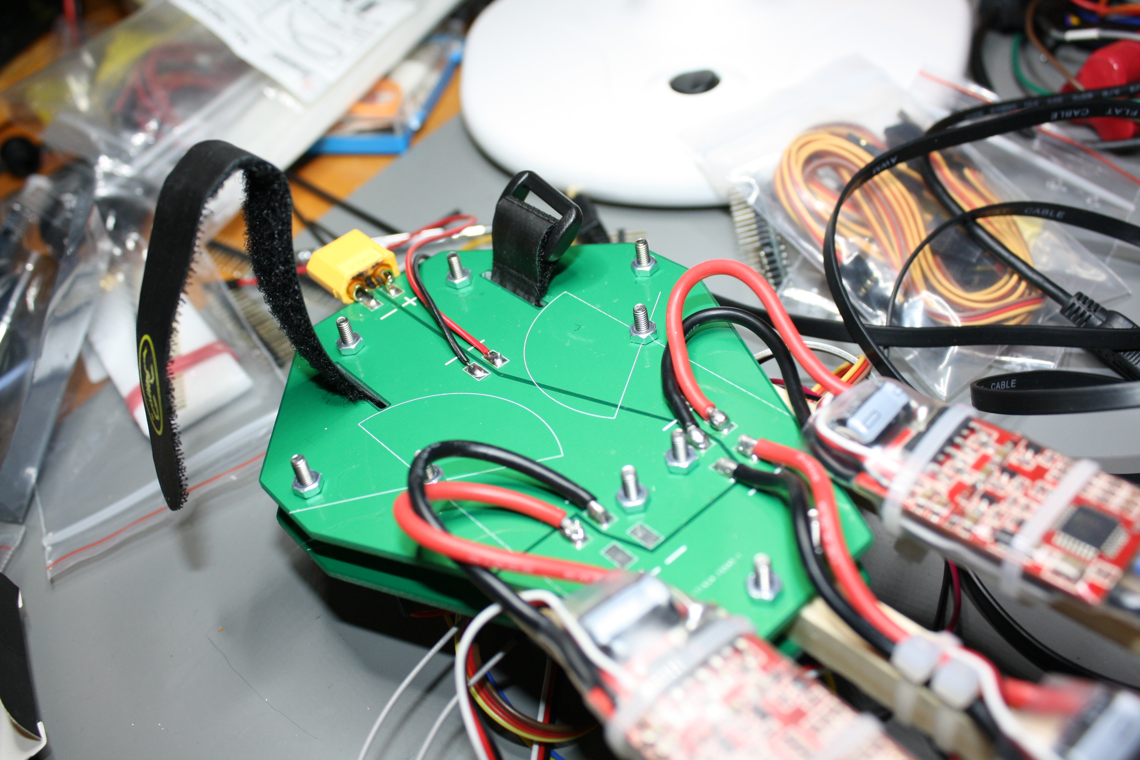
Power distribution
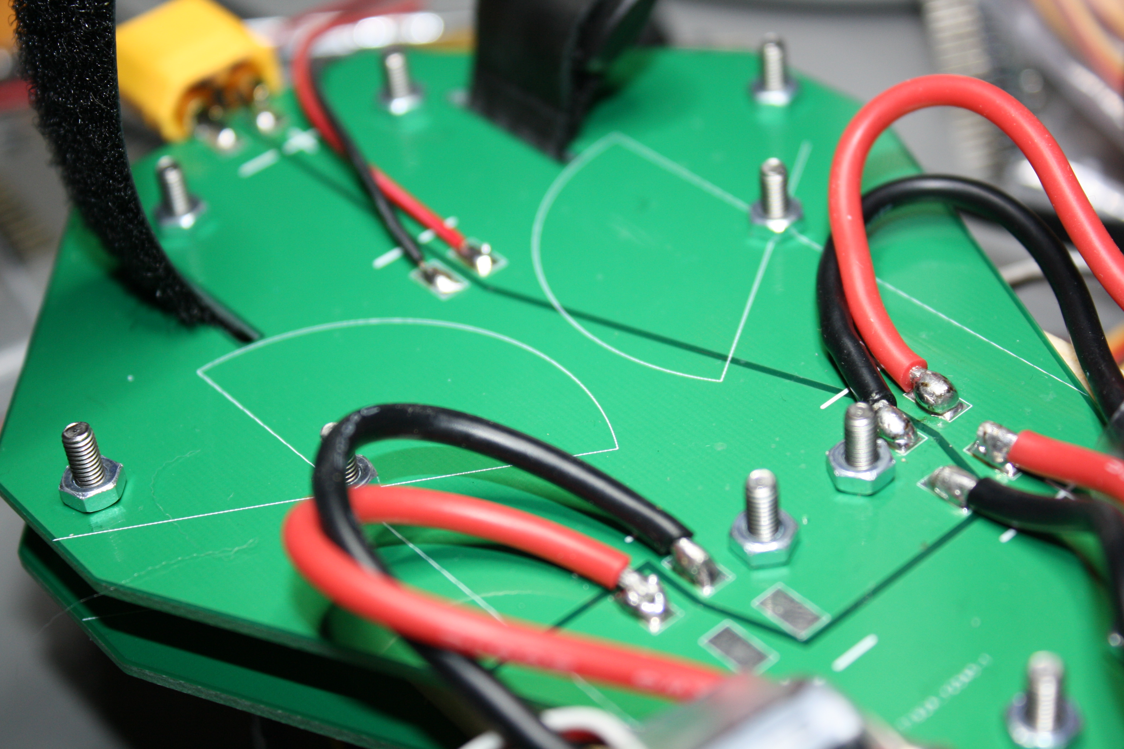 |
| Those solder joints don’t look too good. I should probably redo them before something bad happens. |
Also the screws are way too long and I didn’t have lock nuts, but I hope that the generous amount of thread lock I applied after taking the picture will hold everything in place.
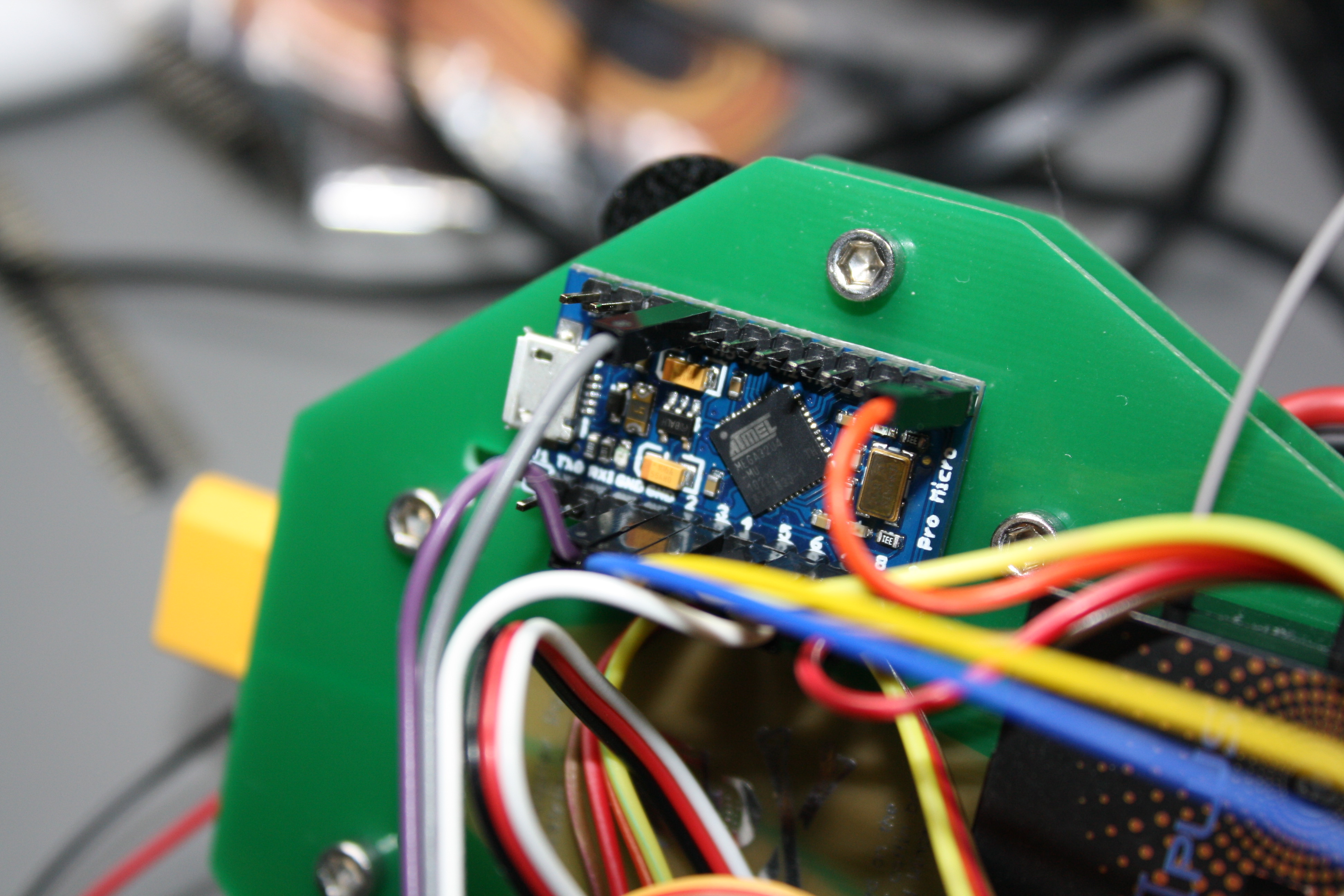 |
| Just a cheap Arduino clone. Please move along. |
Electronics
I used a Frsky D8-Something RX with PPM output and a Chinese Arduino pro micro knock off running MultiWii with a MPU6050 sensor board, for now. I’m planning on replacing it with a Chinese CC3D knock off later.
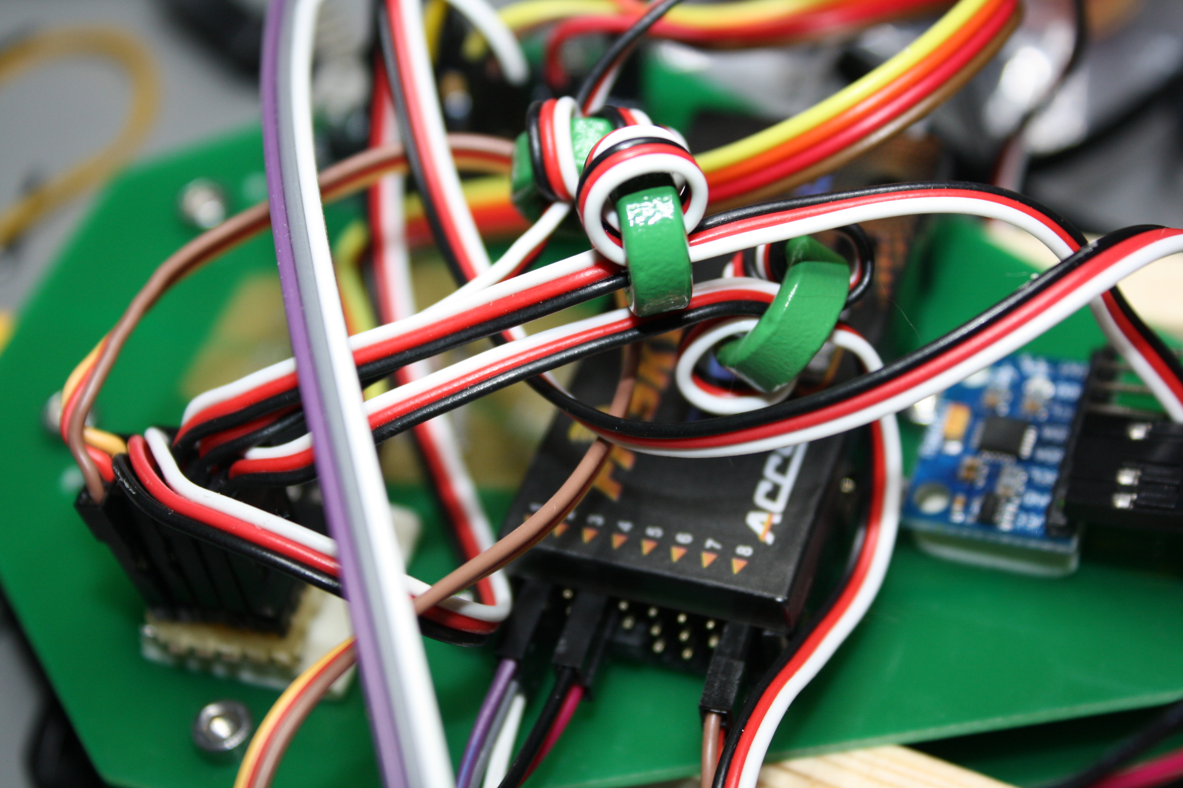 |
| From left to right: Servo/ESC interface board, FrSky RX, MPU6050. And yes, I know the wiring looks like shit. |
I used a bit of protoboard to interface the Arduino with the ESCs. This might go into a later version of the frame, along with an I2C Bus, to ease playing around with different kinds of sensors. Oh, and a voltage divider wouldn’t hurt either, I guess.
Setup/Test flight
I’ve begun setting up MultiWii, but so far the copter wont behave itself. I suspect the PID values are way off, but I just don’t have the experience to tell exactly what is going on. I’ve even got it off the ground for a few seconds once, but I don’t consider that a successful flight, even though it stayed in one piece, because I couldn’t really control it.
 |
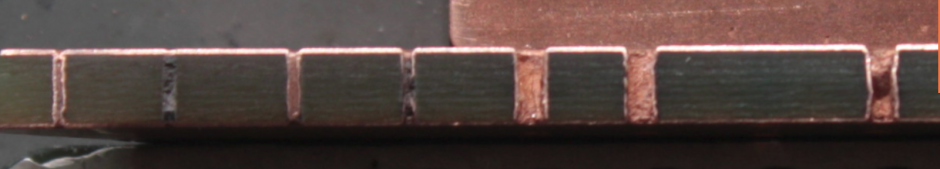
| The beast folded up. The original frame design leaves a bit more sp ace for zip-ties closer to |
After the crash…
- Try again to desolder the original power leads from the ESCs and put custom length leads on them. Don’t chicken out prematurely this time
- Mount the ESCs as close as possible to the motors
- Put the power distribution side of the board on the inside of the sandwich.
- Buy the right length screws and lock nuts for the frame
- Build the Battery/Camera mount from David’s design
- Try shorter and maybe thicker arms
- Put the LEDs and resistors on the landing gears before mounting them to the copter
- Redesign the frame board to use the original arrow shape and put signal distribution, a voltage divider and an I2C bus on it. Hell, maybe even a few LED drivers if I feel like it! After all there is one completely unused layer of copper on there (unless you count the skull doodle)
- Something I don’t know yet. Perhaps something dangerously stupid.