I have a Devo 8s RC transmitter which I adore. What I love most about it, is that there is Deviation, a great open source firmware project for it, which enables you to add transceiver modules for it and (at least in theory) speak virtually any protocol out there.
There is one slight little inconvenience though. The maximum of modules you can add at this time is three (actually it’s only two but there is a way around that), which makes for a total of four. Which means, you have to have four antennas somewhere. Which in turn drove me into learning how to use 3D CAD software (which is a totally awsome experience, btw).
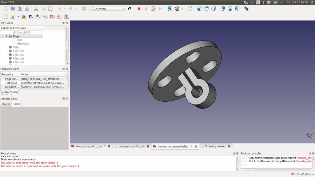
What I tried to do was create a reversible way to mount those four antennas as well as the quite chunky Multimodule itself (although I didn’t think of that until later, of course). If you remove the stock antenna mount, you are left with a 20mm diameter hole with a 4.6mm rod going through in the middle. So I came up with a disc a little wider than the hole to mount the antennas on, and a little clamp that would be used to anchor it on the rod. The whole thing was intended to be laser cut out of 3mm acrylic with two clamps back to back for added stability.
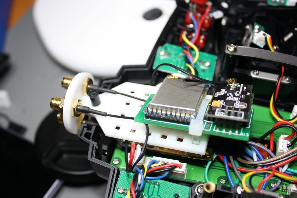
It actually kind of worked but I still hadn’t figured out how to mount the module yet. I wanted some kind of mounting plate with holes in it so I could just ziptie the Multimodule to it. So what I came up with was this:
This is the version I am using right now and so far it works great.
I didn’t mount the fourth antenna yet because the A7105 module came with a piece of wire instead of a U.FL connector. But then, anything I would fly with that particular module, I wouldn’t fly very far anyway, so I didn’t bother to either order and wait for a connector to put on there or just botch a cable on there.
Originally the whole contraption was meant to be press fit, but I soon realized that was never going to happen. Not with the laser cutter at our hackerspace and my patience, at least. So a liberal amount of high viscosity superglue did the trick instead.
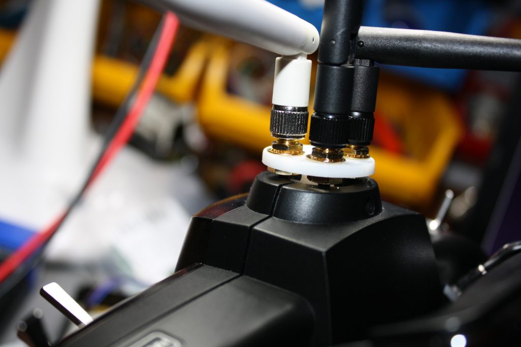
The gap between the enclosure and the antenna mount is intentional. The nuts on the SMA connectors wouldn’t fit inside.
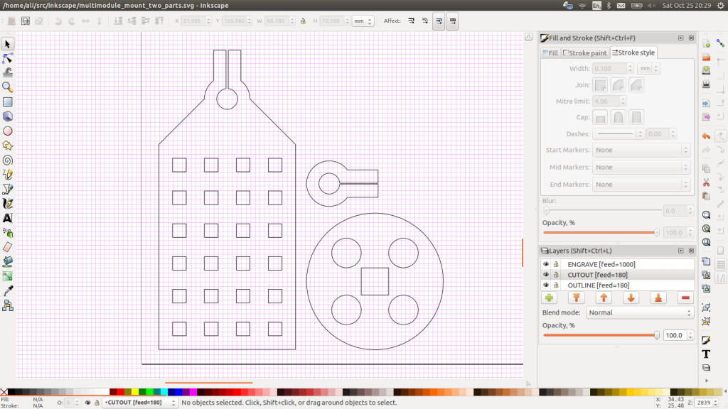
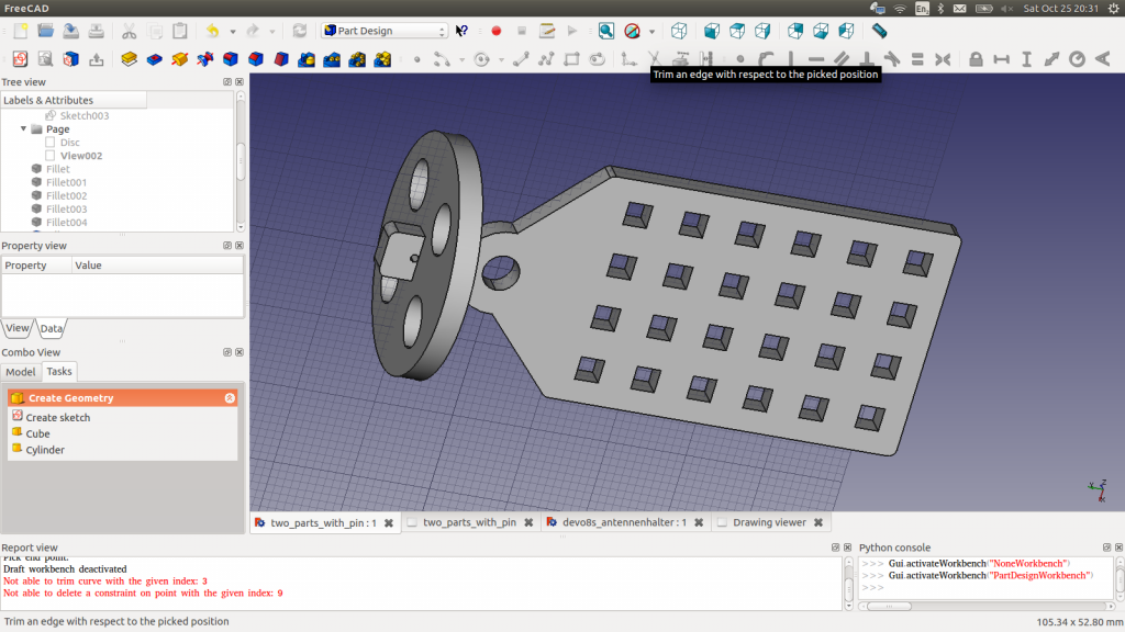
I was still a bit worried about stability, as there is no anchor for the antenna mount on the outside, so I altered the design another time and came up with this:
On this one there are only two parts instead of three and the module plate protrudes from the antenna mount. It also has a little hole to put a tiny steel rod through, instead of the slit that didn’t really work out. That and (again) a generous squeeze on the superglue bottle should make up in stability for the reduced thickness of the joint.
I haven’t built that one yet and I just never might, because the current prototype works for me, but maybe somebody else will. Here are the files.

