TP-Link based DLNA Music Player

Everybody is building some kind of multimedia stuff with a Raspberry Pi these days. I’m no exception as I also have one connected to my (really shitty Philips) TV, running RaspBMC. But that’s not what this post is about, and it’s also pretty lame, since there isn’t really that much to it.

Objective

I also wanted something to connect to my stereo to play music, but I didn’t want to use a Pi for that for these reasons:

  • It’s rather wasteful. The Pi including a power supply and an SD-Card costs about 50,-€ and I wouldn’t even use most of the hardware it comes with.
  • The SD-Card will break eventually. Depending on how much logging I would forget/neglect to disable, rather sooner than later.
  • It doesn’t have wifi and I have no ethernet in the dining room where the stereo sits.
  • The audio output of the Pi sucks. Plain and simple. It’s about as far from HiFi as Fox News is from being a news network. So I’d have to use an external DAC to get decent audio output from it.
  • It’s about as lame as using a Pi for video playback. Perhaps even more so.
Now that we have established that a Raspberry Pi just isn’t the right tool for the job, what is? A cheap chinese wifi router seems to be a perfect fit, provided it has enough power to decode MP3s, OGGs, and FLACs (and it has). The only thing missing is the audio output, but that can be added as a USB device, the same way it would have to be done with a RasPi. Also, it obviously has wifi and it’s a lot cheaper than a RasPi.
Hardware

I went for a TP-Link WR841N V7.2 because that’s what I had lying around. I also had a Behringer USB DAC collecting dust. If anyone wants to replicate this project, I’d recommend getting another kind of router, since the WR841N doesn’t have a USB port. The processor does, however, but I had to solder the D+ and D- wires to some tiny ass resistors on the board and generate the +5V from the routers 9V supply voltage myself. Any version more recent than 7.2 of the router doesn’t even have traces for the data pins and the processor comes in a QFN package, so you’d have to cut away part of the processor package and solder the data lines directly to the processor pins. Some people have done that, but I’m just not that sick. I might be a cheap bastard, but putting a Dremel to a QFN package is where I draw the line.
Somewhere left of the processor are R601 and R602 where D+ and D- surface

Other than adding those data lines the hardware side of this build isn’t too interesting, so I will spare you the details.

Botched up a 7805 voltage regulator and a few caps on a piece of perfboard
OpenWRT

Since these cheap routers only have a few megs of flash, they can only run special embedded Linux distributions like OpenWRT, which is what I am using. But even with that, there was no way of fitting all the needed packages in there, so I added a flashdrive to deal with that. Since the processor only has one USB port a USB hub was also needed. That was actually the only thing I had to buy for this project.
The OpenWRT project provides lots of documentation about building minimal images and putting its root filesystem on an external storage, so I’ve done just that. With plenty of storage to install the needed packages, it’s for the hard part: Building the software.
GStreamer and gmrender-resurrect

There are quite a lot of projects out there that achieve a similar goal, but it seems that all of them use mpd for streaming. Frankly, I don’t like mpd very much, mainly because all clients I’ve seen so far lack in usability. Also, it seems to me that while it even supports gapless playback, it’s unlikely to be adopted by manufacturers (if it were, there would be a few commercially available players by now). DLNA on the other hand looks like it’s quickly becoming a de-facto industry standard as it already has been adopted by some very reputable HiFi manufacturers like Linn, Marantz, Denon and others.

For DLNA-Support there is a project based on the gstreamer framework, called gmrender-resurrect, and also an OpenWRT port of it. OpenWRT packages can be built using either the OpenWRT SDK or the OpenWRT buildroot. If you can live with the hopelessly outdated gstreamer packages provided by OpenWRT, it’s just a matter of building the gmrender-resurrect package and you’re done. I couldn’t, however, so I built packages for the current version of gstreamer, too, which took me forever.

I’d like to point out that no real coding or porting work was done on my part. I just updated and fixed a few Makefiles to make it build. All the real work was done by other people.


The finished thing: Router, USB-Hub, Flashdrive, USB-DAC
All patches needed to compile gmrender-resurrect and gstreamer (including plugins) are available on my github.
What it can do

These little routers are really amazing. With this I am now able to play music from any DLNA source (fileserver, phone, tablet, laptop, you name it…) to the stereo in my dining room. I’m using BubbleUPNP on Android as control point and it really works great! Also, it still acts as a WDS-router.

Where to go from here

There’s a lot more that can be done, given that all the LEDs and buttons in the router are actually GPIOs. So adding a LCD and putting it in a nice enclosure (like an old CD-Player) with Play/Pause/Skip-buttons should be pretty easy.

Posted in Digital, Linux | 4 Comments

Frankensockets

I hate tinkering with AC mains. But if you want to get “real” things done around the house there is no way around it. So before this goes any further, here is the disclaimer:

AC mains power is dangerous. It can kill you and/or burn your house down if you are not careful. Unless you know exactly what you are doing, DON’T TRY THIS AT HOME!

That being said, AC mains is no rocket surgery either and probably no one in their right mind would call a union electrician to hook up a lamp.

So, what is there to switching mains? Not much, actually, it’s just a sufficiently rated relay to switch the hot or neutral wire (it doesn’t matter which, either will break the circuit and prevent current from flowing).

There is a variety of readily made hardware available that will accomplish this but from my point of view all these products are flawed: The ones that work reliably are expensive and the cheap ones are unreliable.

Hardware:

I had a few very cheap and extremely unreliable ones around, so the obvious solution was to gut them and use the enclosures for my own design.

I got these about 20 years back, as you can tell by the grime.. The set of four was about 30 DM, back in the day.
All those certifications… Must be good stuff inside…


The enclosure looks quite nicely engineered. But what is it with that crappy and kind of burned looking circuit board?


Yuck! This isn’t even a cap dropper, this is basically just a resistor on a mains wire, and it looks fried up pretty good. How did they get all those safety stickers with this?

The design itself is simple: Just hook up a relay to an Atmega with an RFM12B. If there wasn’t the issue of a power supply. Looking at commercially available solutions there seem to be mainly two options: Go with a full blown switch mode power supply or implement some sort of ultra cheap non isolated cap dropper type power supply. Both have a list of pros and cons:

SMPS pros:

  • isolated from mains
  • efficiency
SMPS cons:
  • size
  • price
Cap Dropper pros:
  • size
  • price
Cap Dropper cons:
  • not isolated from mains
  • inefficiency
Looking at the pros and cons it’s obvious why most commercial products have cap droppers. They are dirt cheap to produce and the producer or vendor really doesn’t give a crap about their efficiency. After all it’s your power that’s wasted, not theirs. Mains isolation is irrelevant, since the whole circuit is safely tucked away inside the enclosure.
To me as a hobbyist priorities are a little different. Efficiency totally outweighs initial cost. What good is a power supply that takes only 50 cents to build if it eats up 10 € in electricity a year. Not to mention mains isolation. I’ve known myself for quite some time now and I know that (probably like everyone else) with growing routine and confidence I tend to get sloppy. And that’s when I get hurt or accidentally blow up my gear. So no cap dropper for me.
An SMPS on the other hand would have to be reasonably cheap and, even more importantly, small. Given the simplicity of my overall design and the overwhelming choice in available SMPS, choosing a suitable one proved to be the most challenging part of this project.
These are really nice. But also very expensive


There are SMPS-Modules that would be ideal for this project, but unfortunately those cost about 30 € a piece, which is about three times of what I intended to be the cost of a completed socket, so those are out.

Then there are those really slim iPhone chargers, but those also cost about 20 € (used to be 30 a few months ago) and my religion forbids the purchase of apple products anyway, so those are out, too. But then there are those fake Apple lookalikes, which cost only 2-4 €. Couldn’t I just use those? I decided to give it a try and ordered a bunch from Ebay or Amazon or so. Of the six I got one blew up right away, so I sent them all back the same day.


The switching transistor bent over to the secondary side was the reason this
one was rejected
After ordering a few more similar, but slightly more expensive types, cutting them open and discussing the pictures on the net I finally found this one:
Almost as tiny as the “Apple” chargers

It’s cheap, small and at first sight not too dangerous. At least there were no reviews about these things blowing up all the time.

This looks more like it. A nice big slot between primary and secondary side and no parts hanging over from the dangerous side.

With this out of the way I was finally set to go. To make the PSU fit the enclosure I hat to cut it along the slot that was already there.

Nice fit. The mains side of the PSU is on the left

Space was an issue with this project. I could have easily thrown those old sockets out and gotten new ones with bigger enclosures, but where would be the fun in that?

So, after I pulled out that deathtrap load of crap PCB I found inside, I went through the usual process of measuring the enclosure and designing a new board in Eagle.

Boring.


Also quite boring. This is hand routed, and I needed six jumpers. Lame.

To accommodate the PSU, the relay and my controller board I had to make two PCBs: One for the controller and RFM12B, the “cold board”, and one for the relay and the PSU, the “hot board”.

The “hot board”. This will only contain the relay and mains connections for the PSU. This isn’t its final form. The leftover copper at the lower edge of the board was of course removed. At the left lower edge I hat already removed a bit too much.
To connect the PSU to my adapter board, I just bent two regular pin headers and soldered the PSU’s mains contacts to them.


The “cold board”: This will contain the RFM12B and the Atmega


The push button and the LED are still missing.


Note the absence of parts on the right hand side of the board. That will be on top of the mains side of the power supply.

The controller board would be on top of the PSU. To eliminate the risks of accidentally shorting anything to the mains side of the PSU I arranged all
parts on the controller board so they would be a safe distance from all the scary mains stuff.

The hard part is done. Those heavy duty mains wires weren’t too much fun to work with.


Almost completed. Now only the wires from the PSU and to the relay need to be connected.

The prototype worked perfectly, so I was ready to go into production…

Three more controller boardsI was smart enough to put three boards on a panel, but not to think about routing the outlines of the boards. m(


…and the PSU/relay boards.

There was some time between building the first prototype and finishing the rest of the bunch, so it slipped my mind, that I used a m168p on the prototype and m328ps on the other three, but it wouldn’t have changed anything, because I hat no 168s left. Well, now I have to have a type A and a type B in my Makefile. Never mind.

The semi finished sockets on the “assembly line”.

They work beautifully and the power supplies are quite efficient. With the relay idle they draw about 0.2W and with the relay active it’s about 0.6W. I vaguely remember, that the original circuit drew about 2.5W, no matter what. I could maybe reduce the active power consumption another bit by driving the relays with PWM, since they need a lot less power maintaining an active state than switching to it, but that’s for another day.

I finally got around to adding the LEDs. The buttons are still missing, though.

Software:

On the code side there are a few things to mention:

The sockets tie into my sensor and home automation infrastructure, I have yet to write a post about. Basically every type of device uses a separate rf12 node id, which is shared among all devices of that type, which in turn all have their own individual mcu ids, which are stored in eeprom and can be set dynamically.

When a virgin socket is powered up for the first time its mcu id will be 0xFF, because that’s the default value of untouched eeprom. If the id is 0xFF, the controller will go into a loop where it sends a packet every second announcing that its id is unset. In this mode the only command it accepts is one that assigns it an mcu id, which is then written to eeprom.

With the mcu id set, the controller will enter its normal mode in which it will listen for packets with matching node- and mcu id and do what it’s told. In this mode the relay can be turned on and off or queried for status.

Conclusion:

This was a fun project, but I wouldn’t go about it this way again. The power supply alone is way too much hassle. In the meantime I’ve learned about a nice sounding switching regulator for transformer less power supplies (and ordered a bunch), so I’d sacrifice mains isolation for simplicity, but I won’t play around with them without an isolation transformer. That would probably be really painful.

I’ll probably stick to buying some cheap sockets and gutting them, because that’s the easiest and cheapest way to to get my hands on suitable enclosures, but I’d choose something nice and big, and maybe even a cheap brand name, to improve the odds that the same model will be around for a few years. After all, I don’t want to have to change my “Frankensocket” design around all the time.

I’ll also make some with screw terminals or just wires sticking out, instead of sockets, that can be hooked up to ceiling fixtures. Those would easily fit in a small project box or maybe even a piece of heat shrink tube.

I must add that I’m not the first one to do this. There is another, very similar project here.

As usual the code and all PCB design files are available at github.

Posted in 868MHz, AVR, Digital, Wireless | Comments Off on Frankensockets

Coming up…

There wasn’t a lot of time in the last few months to write new posts, so there aren’t any.

But there was time to finish some long overdue projects, move some other ones up the queue,  and think up some new ones. So here is the list:

Finished Projects:

  • RC mains sockets and power strips (RFM12B+AVR controlled, of course)
  • RC Doorbuzzer (RFM12B+AVR controlled, too)
  • Repair of an old, built like a tank, lab bench power supply
  • Rewrite of my wireless sensor and home automation network code

Almost finished:

  • ESR-Meter (without RFM12B, but still with an Atmega)
  • Solar powered sensor node hacked from a cheap garden light

Still need some work:

  • Wall switches to go with the mains sockets
  • Hack annoying toddler toys so I can mute them remotely and build some new ones
  • Long range garage door remote
  • Build a “Lab-Node” with voltage dividers and optocouplers for long term measurements
  • Build/Buy an isolation transformer
  • Play around with non isolated mains power supplies
  • Build a dummy load
  • Repair and and complete re-cap of an old NAD 3020 amp
  • Build a little robot to creep into an old sewage pipe to check it’s condition
  • Build a bathroom if the condition of said pipe turns out to be OK (I’m a bit scared of this one)
  • Rewrite of the powermeter code
  • ???
  • Profit
Posted in Uncategorized | Comments Off on Coming up…

RUWIDO Merlin IR-USB-HID Receiver

There are these very neat IR Keyboards for sale at a German surplus retailer. At only one Euro they are a steal, but the reason they are this cheap is that they come without a receiver. So to the average person seeking a nice keyboard for their living room media center PC they are useless.

I bought one a few months back when they were still 2,95 € and tried to get it to work with LIRC, but had little luck. It kind of worked in raw mode but the key repeat rate was insane and also this wasn’t what I was after: I didn’t want to use it as a remote control with LIRC, but as a regular HID keyboard instead.

These keyboards were discussed on quite a few (mostly German) forums on the web, and someone even came up with a decoder for the IR protocol, but so far nobody seems to have written something that would act as a USB HID keyboard. So I had to do it myself.

I did it by simply combining the IR decoder with the V-USB project, which implements a USB HID driver on any old AVR device (not those expensive “U” types, which come with hardware USB).

It should run on any ATMega44/48/168/328 and even on the ATMega8. Which is quite nice because there is a type of USB ISP programmer called USBASP, which is also based on V-USB (I think), and those are available on Ebay for about 3,- €.

So all that’s left to do is to get one of those and solder a IR-receiver to it, so I can get it off the breadboard.

The schematic is really simple. And the best thing is, the USBASP already contains everything everything except the TSOP1756 !

As usual, the code can be found in my Github-repository.

Posted in AVR, Digital | 2 Comments

Debugging the garage door remote

A while ago I built a little remote to open my garage door (well, not actually my garage door but the one of the house I live in, but who cares). But the greedy kid I am, I wasn’t satisfied with just opening the garage door with it. After all it has four buttons, and so I planned on also using it as a remote for my yet to be built home automation system (a few parts of it already exist, but there is a lot of work to be done before I can really call it that).

The problem was that it had a nasty bug which was really hard to track down: It would work as intended for some time (sometimes hours, sometimes even days), but then, all of a sudden it would hang. And not only did it seize to work, it also stayed in some state where it consumed lots of power and ate up the battery in no time. This was far from usable in real life.

I had heard of a little thing called watchdog timer, which could reset the MCU if it hung. So the first thing I did was to add this watchdog timer to my code. Sure enough that didn’t fix my problem, so I tried everything I could think of from incrementing counters in EEPROM after every “real” instruction in the code to hooking up oscilloscopes and logic analyzers. But the only thing I found out was that it somehow, sometimes would get stuck in some weird kind of a reset loop.

When I ran out of ideas of what else to try I started badgering people on various internet forums. And after trying all sorts of changes to the code that people suggested, someone came up with the idea of deliberately causing a reset (among a few other things). I implemented that idea in my code and what happened was, that now every time I caused the reset, the MCU would hang. That may not sound like a good thing at first, but at least now I could reproduce the bug!

After that all it took was a bit of searching the web until I found out about a register called MCUSR, the MCU status register. Turns out that if the watchdog wants to reset the MCU, it writes some value to this register that would cause the MCU to perform the reset. But for some reason it doesn’t get cleared after the reset is done, causing the MCU to keep resetting itself until the battery is dead or the world ends, whichever comes first.

So in the end all I had to do was to set the MCUSB to zero right at the beginning of the setup() routine and all of a sudden the reset would be performed as intended and the MCU would work again. For now. I’ll have to give it a few weeks to really call this case closed, but I’m pretty confident that this was it.

All that’s left to do is to say a big THANK YOU to all the people who tried to help me solve this mystery, and especially JohnO on the Jeelabs forum, who came up with the idea of causing that reset on purpose (although he might have had something completely different in mind than crashing the MCU every time the reset fired).

The updated code can be downloaded here.

Posted in 868MHz, AVR, Digital, Wireless | Comments Off on Debugging the garage door remote

Building Arduino Sketches without the IDE

I really love the Arduino, because after all it was what started all this.

The one thing I don’t like is the IDE that comes with it. It’s not the IDE’s fault, It’s just that I’m a console guy and I don’t really like IDEs in general (and yes, I’ve seen others and I think this one is not particularly good). Luckily there are ways around it, like Makefiles that automatically include all the needed libraries and even upload the sketch to the board. There are several of these out there, and I went with this one which is a slightly modified version of this one. The Makefile is pretty good as is, but I added a few minor changes:

  1. The Makefile can search for libraries in ~/sketchbook/libraries, but instead of the ~/sketchbook folder I use ~/src/arduino, so I just replaced that.
  2. It reads the boards.txt file in the Arduino installation directory but I have my own boards.txt in ~/src/arduino, where I added my own boards, so I changed that path, too.
  3. The setup howto suggests that you symlink the file to your sketch-directories, but if you do that, you’d still have to set the environment variable $BOARD to the right type, which I found a bit tedious. So instead of symlink it, I create a new Makefile in each sketch folder that contains only two lines: The first one sets $BOARD to the board type that sketch uses, and the other just includes the original Makefile.
The result is a very tidy build system with no redundancies whatsoever.
As usual everything can be downloaded in my github repository:
Posted in AVR, Digital | Comments Off on Building Arduino Sketches without the IDE

Smartmeter III – blinking LEDs

This is a short one. At least compared to the usual walls of text I post.

Due to the nature of my water heater (a continuous-flow-type), it’s power consumption is highly dependent on the water pressure and flow-speed. The more and faster the water flows, the more power it consumes. Apparently this happens in three stages. The first two turn on immediately as you turn on warm water. But the third will only com on if needed, i.e. if the water consumption continues to increase. Also these three stages are connected to three different mains lines, which means, they get counted separately.

Saving energy, resources and money is fine, but sacrificing creature comforts for it? No way!
When I take a shower I want it hot. And I don’t want it trickling down on me, either.

That’s not a problem with my new water (and thus electricity) saving shower head. What is a problem, though, is that the water flow has to be adjusted just right to keep the third (and greediest) stage of the water heater from turning on.

So to be able to see what the water heater is up to, while in the shower, I built this little thingy:

It’s just a Jeenode with a few LEDs

The yellow, green and white LEDs blink if there’s a pulse received for one of the three mains lines, and the red one will blink if a packed got lost. Right now it’s powered with a single AA battery, but that lasts only a couple of days, so I’ll have to add a little power supply, probably from an old phone, since I have plenty of those.

The code to drive it is here:

https://github.com/alibenpeng/powerblinker.git

Posted in 868MHz, AVR, Digital, Wireless | Comments Off on Smartmeter III – blinking LEDs

Smartmeter revisited

Einstein once said that only two things were infinite: The universe and human stupidity. The former even he wasn’t sure about, and the latter I found out the hard way. But I’ll start from the top:

I’ve had my smartmeter running for a while now and since the readings looked plausible I assumed they were accurate. Well, they weren’t.

The meters I use generate 2000 pulses of 90ms length for every consumed kWh, and the way I counted them was to collect them for five seconds and then transmit a summary. After a while I found out two things about my power consumption:

  1. The water heater (a continuous-flow-type) consumes an insane amount of power, and
  2. The computer running the metering software also was a bit too greedy for my taste.

I couldn’t do anything about the water heater because it’s installed permanently and after all it’s not even mine, but I could try and tame it’s power consumption by reducing the water pressure and/or the flow speed by using a water saving shower head. As a side effect I’d also reduce my water consumption. Two birds with one stone! And the PC running the metering software also had to go.

To get rid of the PC I had to rewrite the metering software from scratch, because the software from the volkszaehler.org project I was using is based on a full-fledged LAMP-stack (Linux, Apache, MySQL, PHP). The main problem was the MySQL-database, as this keeps every reading I ever took and has to access them all at once every time I’d wanted to view my consumption graph (remember, I took readings every five seconds, so there were a LOT of values in there).

I opted to use something called RRDTool instead. This is a nifty little tool, well known to sysadmins around the world to keep stats about routers and switches, system loads and whatnot. Since there are usually a lot of data sources too keep track of, the databases have to be kept small. The way it achieves this is to use fixed size databases of different resolutions and aggregation functions to consolidate older data.

While I was at it, I also changed the way I collected the pulses from the meters from the five-second-summary-method to transmitting every pulse as it came in. This is where things started to go South…

Before…

But the really stupid thing I did was changing something that drastically influenced my power consumption (the shower head) and the way I collected and processed the consumption data at the same time.

The result was that I grossly overestimated the savings from changing the shower head and thought I’d cut my consumption by about 50%, since that was what my new readings suggested. I never even bothered to check the “official” meter from the power company, which finally bit me in the ass when the next power bill came in.

…after…

Only then did I find out that my readings were way off! They may have looked plausible, but weren’t anywhere near my true consumption.

After this wake up call I started to investigate the error. At first it looked like the new way of counting pulses was to blame, so I changed that back to the old way. That gave me way higher readings but by then I had grown suspicious if those were correct. They also weren’t.

So the new method was obviously loosing pulses while the old way was counting pulses that weren’t there. The one thing both had in common was the way they went into the controller:

When idle the controller was in sleep mode and an incoming pulse would cause an interrupt to wake up the controller and send out a packet or increment a counter, respectively. Since the driver for the RFM12 transceiver is also heavily based on interrupts I figured that might have been the problem. I also had some code to blink an LED using the Arduino delay() function, which is a really bad idea when using interrupts at the same time, but I threw that out first and it didn’t fix the problem.

So I changed the code to poll the inputs instead of sleeping and waiting for interrupts and that seemed to help with the lost pulses.

But things only got weirder: Now some pulses were counted twice. So I started counting milliseconds between pulses and it turned out there was some kind of bouncing about 75ms after some pulses, while others looked OK.

I knew that mechanical buttons tend to bounce, but this bouncing would occur in the first ten ms after the button was pressed, not 75ms later! 75ms is close to eternity, even for a tiny and slow 8 bit microcontroller. A real computer could go fetch a coffe and have a smoke in 75ms! Also there weren’t any mechanical switches anywhere near the circuit I’ve built. The pulses are generated digitally by the counters, go to an optocoupler and straight to the controller.

But I didn’t want to rip the whole thing out of my breaker box and dissect it with an oscilloscope, so I just wrote a little routine that ignores every state change that occurs less than 90ms after the input went low. Think of it as a really slow debouncing routine.

and the real thing (hopefully)

So far my readings look OK, there still is some 0.03kWh error per day, give or take, but that’s nowhere near what my old code produced.

As usual, the code can be found in my github account:


Posted in 868MHz, AVR, Digital, Wireless | Comments Off on Smartmeter revisited

My DIY Smartmeter

This one started with a power bill. One exceptionally high power bill, that is.

I had been reading and thinking about smart metering and smart grids for some time already, and when the bill hit me I decided it was time to act. But where to start? Those kill-a-watt-kind-of-things weren’t an option because I needed to measure the power right at the point where the lines enter my apartment, because I didn’t want to miss anything like the stove or the water heater, which don’t plug into sockets, but are connected directly.

The guts of my Breakerbox:
In the lower row you can see the main breaker on the left
and the breakers for the stove and the water heater.

But I also didn’t really want to mess with my breakerbox if there was any way I could avoid it. So the first things I had a look at were inductive sensors. Only two problems with that:

First, the coil or the ferrite core of the sensor has to go around the conductor you want to measure. So either the coil, the core or the conductor has to be split open to mount it. There are sensors made especially for this purpose, like these: https://www.flukso.net/content/50amp-current-clamp, so this issue could be addressed by simply throwing money at it, because those specialized sensors anren’t too cheap. Actually there are even some DIY projects for these sensors out there.

The second problem is, that these sensors only measure current. We want to measure power consumption and power is the product of current and voltage. So we’d need to measure the voltage, too, if we want accurate measurements. Now this definitely isn’t achievable without a physical connection to the conductor.

So there you have it: No accurate measurement without physical contact to hot wires. Just no way around it. Shit.

This meant, I couldn’t do his by myself. Luckily that’s not that much of a problem, because a friend of mine, who is a certified electrician, had offered to help me out.

The inevitable disclaimer:
Working with AC mains power can kill you! Don’t do it unless you really know what you’re doing!

This also meant, that I didn’t have to awkwardly hack about with current clamps and later figure out how to calibrate and measure the whole shebang, but I now could look at an entirely different concept.

The meter(s):

There are lots of electronic powermeters out there, calibrated and uncalibrated, the main difference being that the calibrated ones are only required if you want to use them for billing purposes.
In my case an uncalibrated one would do fine. These meters have an interface that generates pulses when power is consumed. The pulses are 90ms long and come in different resolutions, 1000 or 2000 pulses per consumed kWh are the most common. Basically they all look like these.
So I picked up three, because where I live it’s common to have three wires carrying 230V (and one neutral wire) going into your home, and all three of these have to be measured.
With all the basic supplies ready it was time to move on to the interesting part of this build:
The controller:
It looks like smart metering is about to become a big thing in Europe, but people are worried about the power companies being able to track their power consumption in such high resolution, and they are absolutely right about it! Just imagine someone at the power company who uses the data to keep track of who is at home and who is not, and sending a team of burglars over to the places where the owners are out for their weekly movie night, or whatever. Or imagine getting a call from the power company with the person on the other end of the line going: “We noticed that you didn’t take a shower for two days in a row now, you really should take more care about your personal hygiene…”
Not wanting to give up this data to the power company is one thing, but there are still many positive aspects about smart metering, like, for starters, I want to know what it actually costs to take a shower.

This is why some folks in Germany started the volkszaehler.org (which roughly translates to “peoples power meter”) project. This project is a really great starting point for everything about DIY smart metering. They’ve got open source software to track the consumption (among other things like temperatures) and several controller designs to connect your meters to the internet (or LAN).


This is the volkszaehler.org frontend.

Actually I only used the power supply and the input driver boards of the project, because the controller board would be connected by Ethernet and I don’t have Ethernet anywhere near my breaker box.

There is another controller design by the same guy that uses Wifi and is compatible to the one I was building, so I tried to use that. That might have even worked had I not tried to make the PCB myself (The guy who designed these controllers also sells kits, but he had no pcb for the wifi-controller):

I have access to a little CNC-Mill capable of making PCBs via isolation routing. This is good for single sided boards (even with SMT parts like TQFPs), but it really sucks to make a double sided board on it. Especially if the board is designed to be made in a real fabrication house where they can make chemical vias, apply soldermask, and so on. The fact that I hadn’t really worked with PCB design software like eagle before, didn’t help.

So I just imported the design into eagle and didn’t care about re-positioning the vias, so that they aren’t below any parts, and milled away… That left me with a semi-functional board where everything would work fine for a while, and then the Wifi-module would perform an unprovoked factory reset.

This was the first design. It was based on a RN171-Wifi-module and an ATTiny2313, and didn’t work. Notice how crammed the area above and on the right of the RN171 is. That’s not only capacitors and resistors, there’s a good deal of vias in there, too.

The bottom side of the beast.

I spent literally months of debugging before I finally decided to can it and start from scratch.

This is what I came up with:


Not much to it. The crucial parts are an ATMega, the RFM12, and the headers to connect to the other board.

Actually this design is derived from the JeeNode, which is (kind of) an Arduino clone with a RFM12B 868MHz FSK transceiver.

Since I was eager to keep things simple this time, and also because this was my first attempt to design a pcb in eagle (or any pcb-layout-software, for that matter), I went with a single sided board. For this all SMT-parts have to be mirrored and placed on the back. But after that epic failure with the first board I also decided to use as few SMT-parts as possible. Luckily the RFM12B is the only one and that’s also comfortably big.

The layout in eagle. Notice the RFM12B on the back of the board

Before you can feed the layout to the router, you have to convert the eagle file to gcode, and while you’re at it, you could just widen the traces a bit, so that you’d have a bit less milling. If you don’t know what I’m talking about, the next few pictures are pretty self-explanatory.

This is what the layout looks like before being “blown up”


This is what the layout looks like after the traces have been “blown up”. The colors are added by the software to ease identifying traces and nets.


The milled and drilled board. I only remembered to take a picture after I already had started soldering stuff to it. Note that it’s no problem to route traces between IC-pins. Also note that some holes (e.g. the ones for the pin headers) are wider than others.

This was done with pcb2gcode which is available at http://sourceforge.net/apps/mediawiki/pcb2gcode/index.php?title=Main_Page.

Unfortunately, there aren’t any more photos of the construction because I broke my phone’s camera function.


The receiver:

– Tell me, Captain Obvious, what good is a single RFM12B radio transceiver if it has no one to talk to?
– Well, not too much, obviously!

Anything with a RFM12B module (and probably others) can act as a receiver for the power meter.
I went and built a receiver into my Asus WL500gP Wifi-router, but you don’t have to:

There are (Arduino compatible) kits and assembled USB-dongles that contain a RFM12B and an ATMega328 available at http://jeelabs.com/, so you could just get a JeeLink or a JeeNode USB and use that.


My breakerbox with my smartmeter in it: Upper row: The controller, middle row on the right: The three meters.


Resources:


I’ve only just started learning C, so the code is probably shit.
Credits:

All PCB milling was done at the Attraktor hackerspace in Hamburg (website in German).
Posted in 868MHz, AVR, Digital, Wireless | Comments Off on My DIY Smartmeter

Garage door remote for real

(featuring my first real factory made PCB)

It’s been a while since I built the garage-door-proof-of-concept-remote. As stated in the according post, the “industrial design” part of the PoC managed to be flimsy and clunky at the same time. So there was some room for improvement.

Back when I still thought the original remote was using 434 MHz, I bought two little “cloning remotes” or at least so I thought. I was eager to save a few Euros, so I got mine from some shady Chinese eBay-shop, and sure enough the ones I bought were far from capable of cloning anything. Instead they just sent out fixed codes, no matter what I tried. Well, at least they did something.
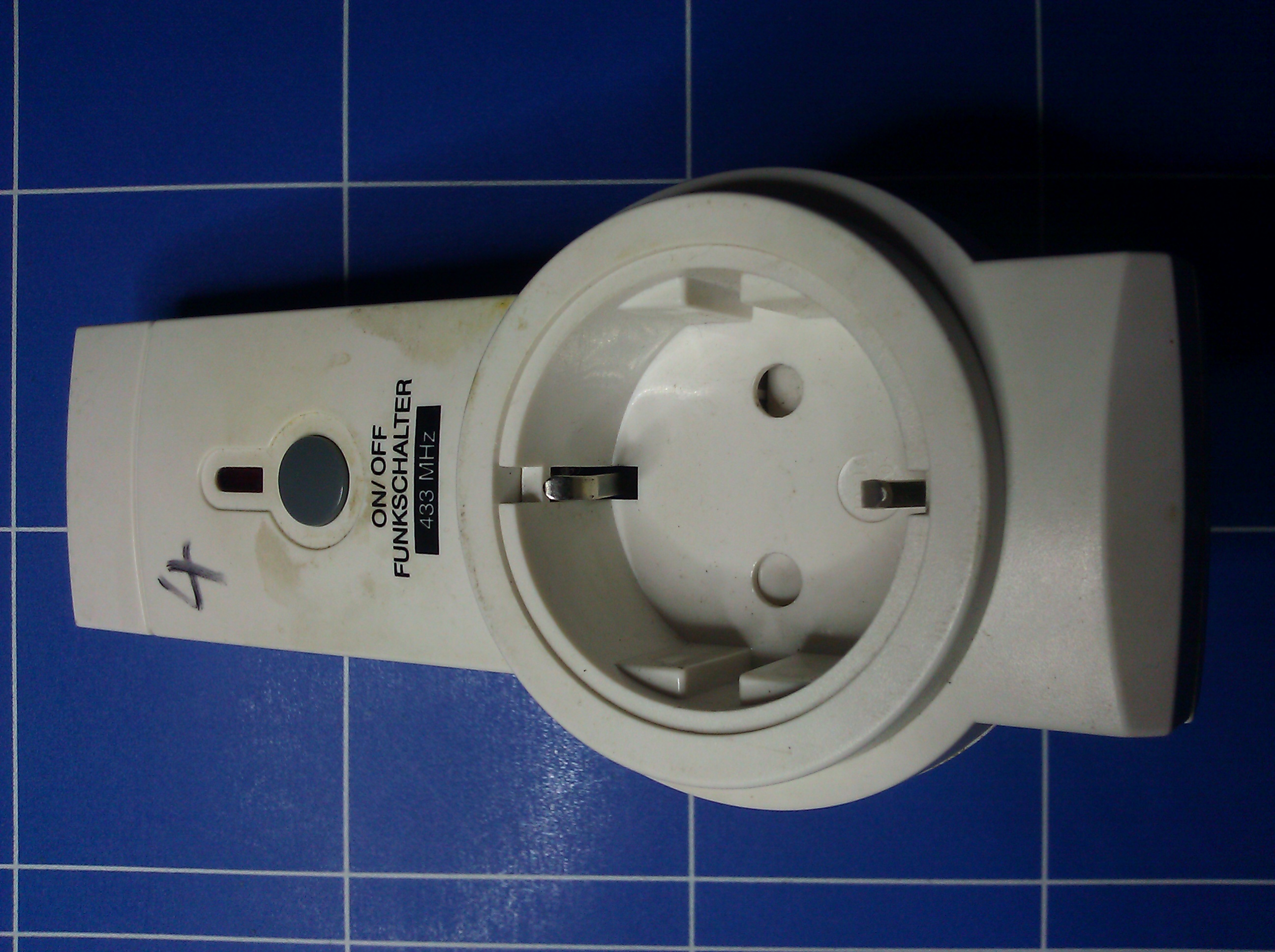
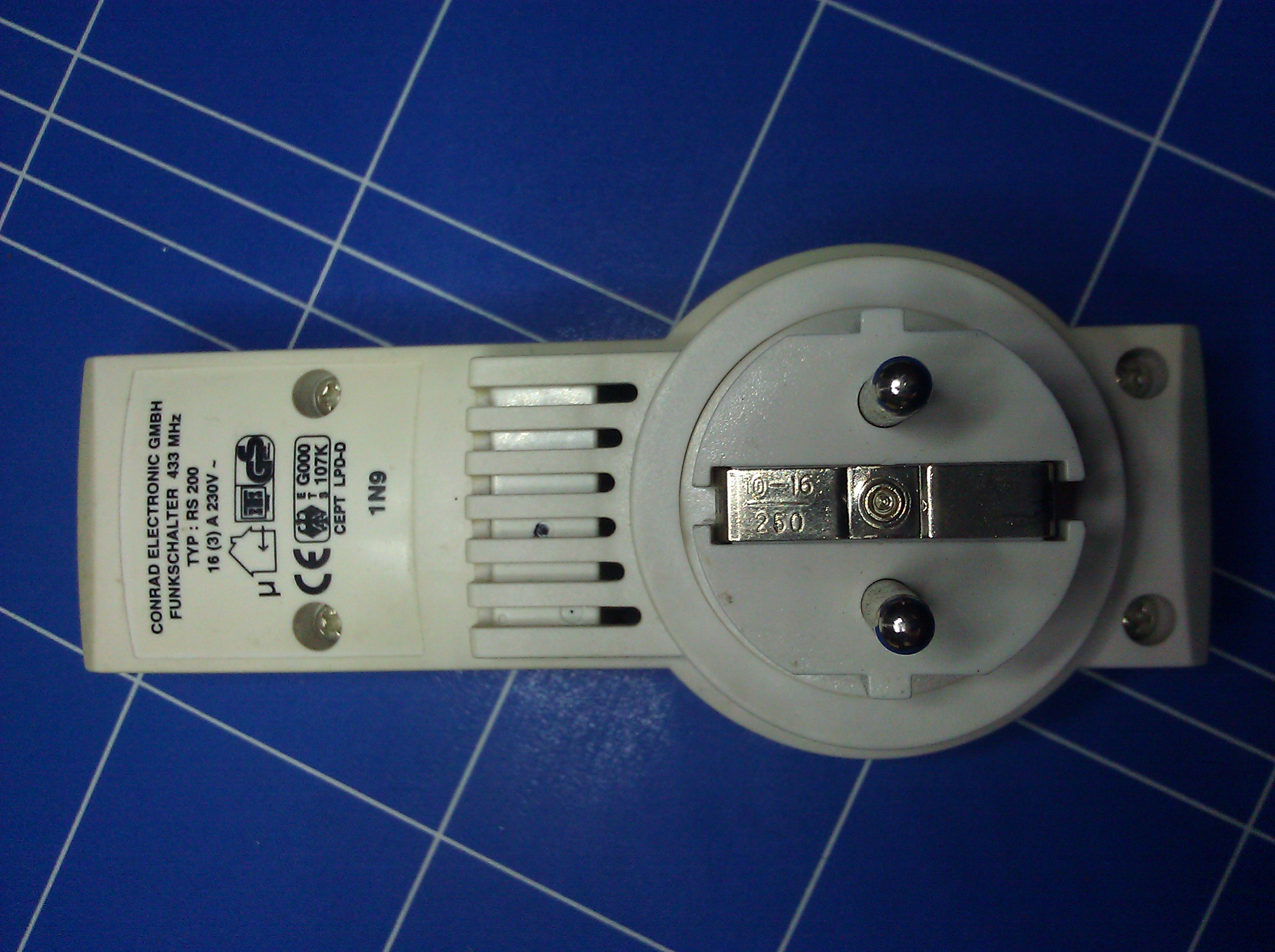
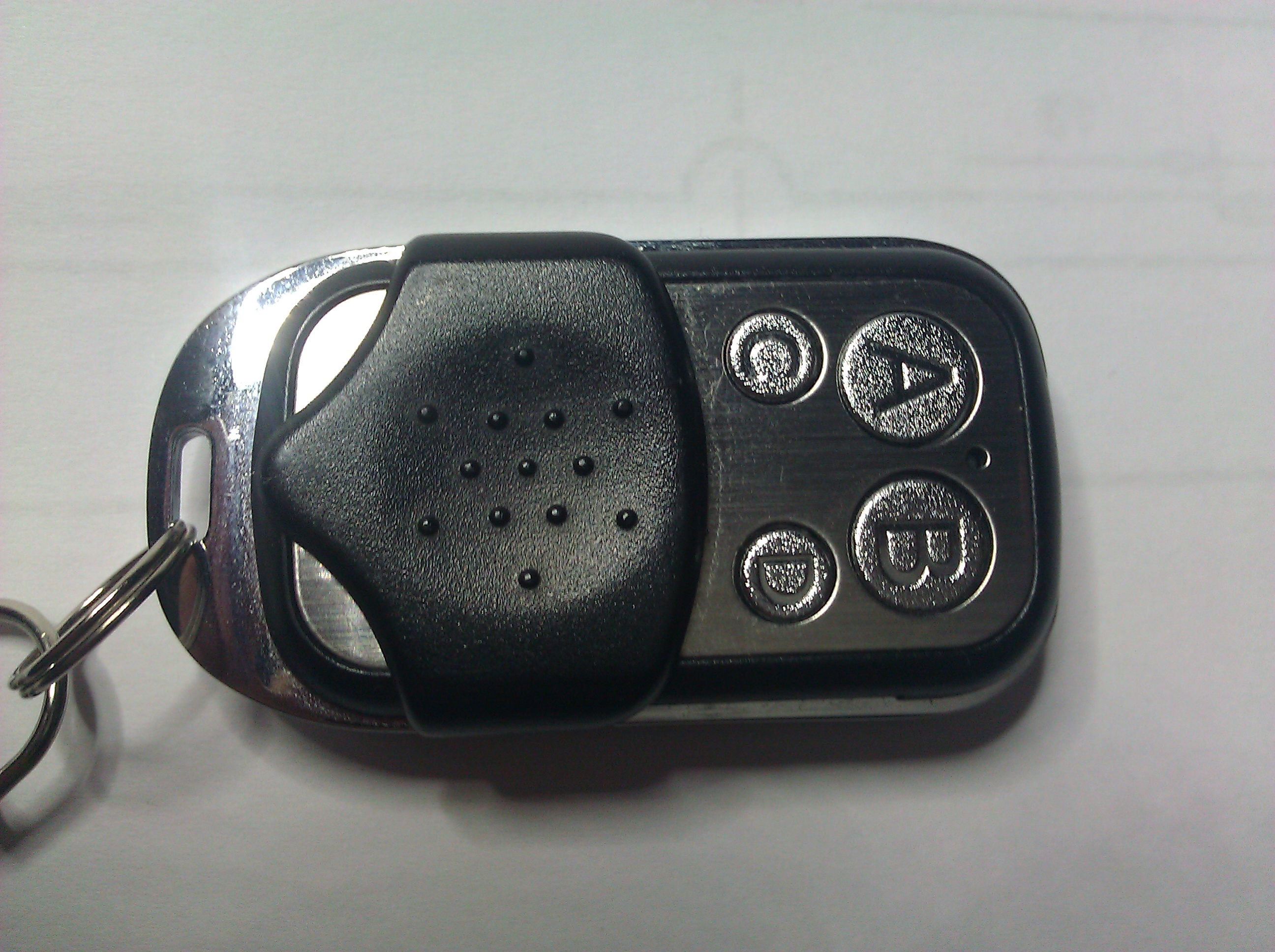
The enclosure.

But even if I had gotten the “real” ones, it wouldn’t have helped a bit, because those still would only work with 434 MHz and I needed 868 MHz.

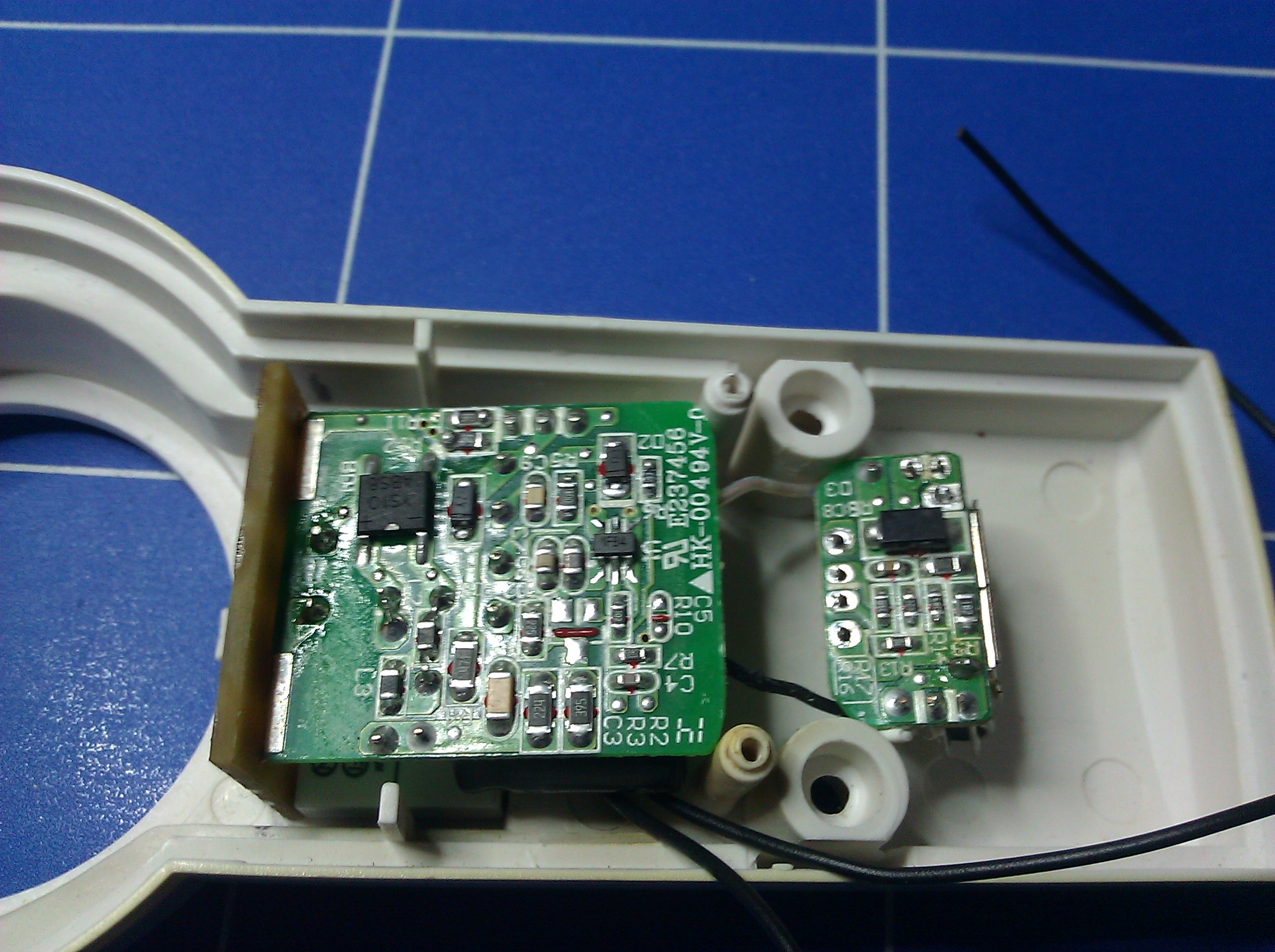
So there I was with my homemade (but working) remote and my two Chinese knockoffs. Even though those were useless, I still liked the enclosure and started wondering if I could just use that and design my own PCB to put inside. I could even harvest a few parts of the original PCBs, like the buttons and the blue LED.

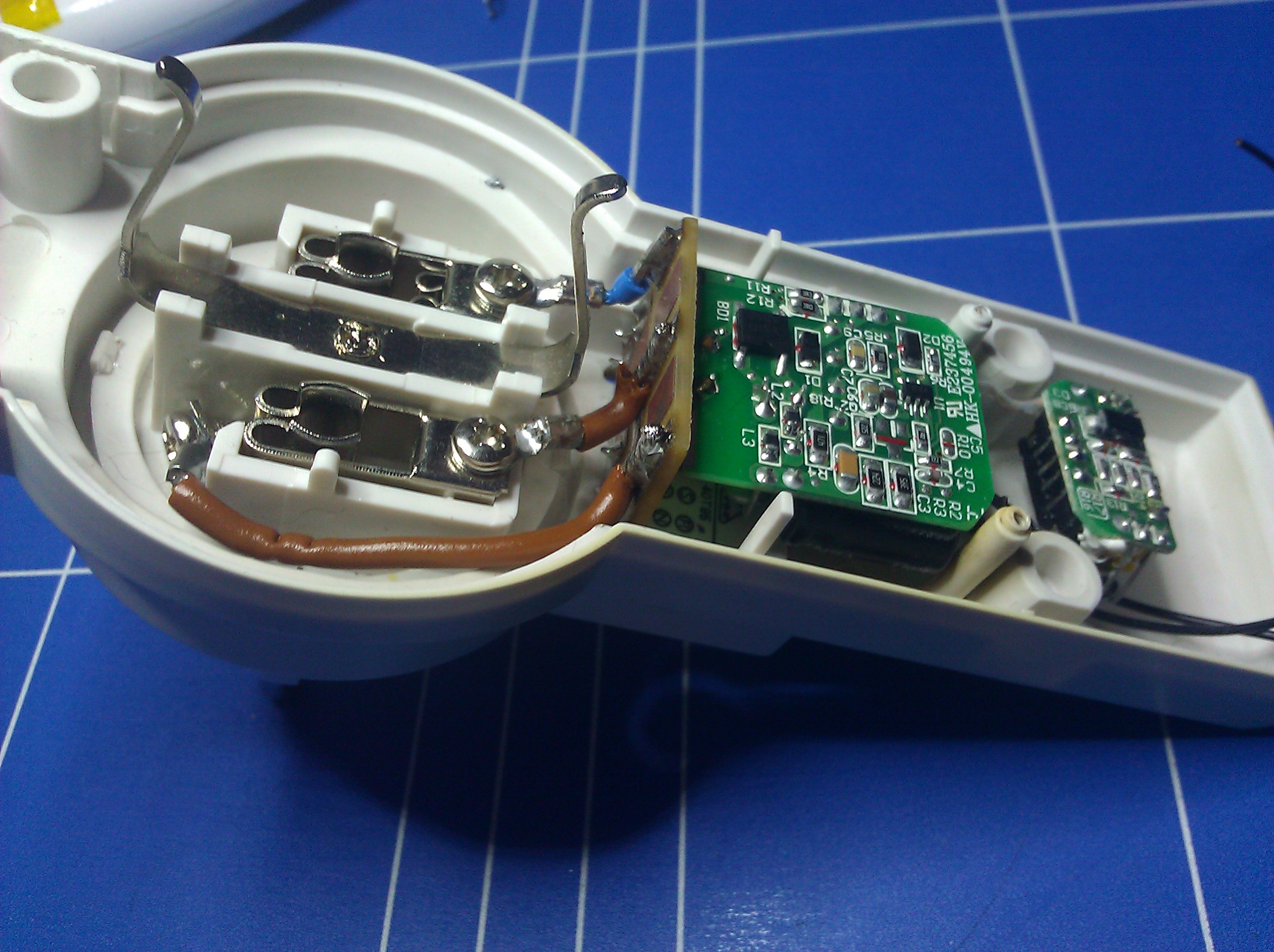
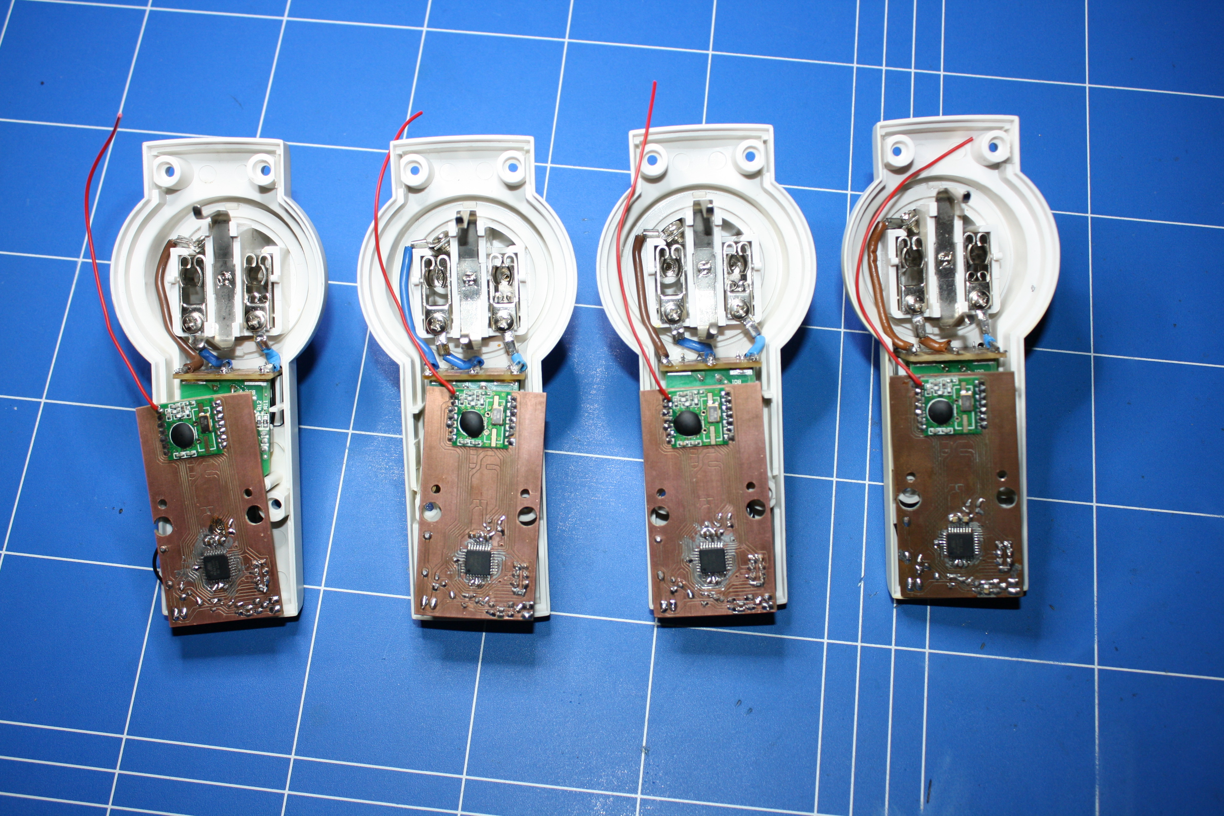
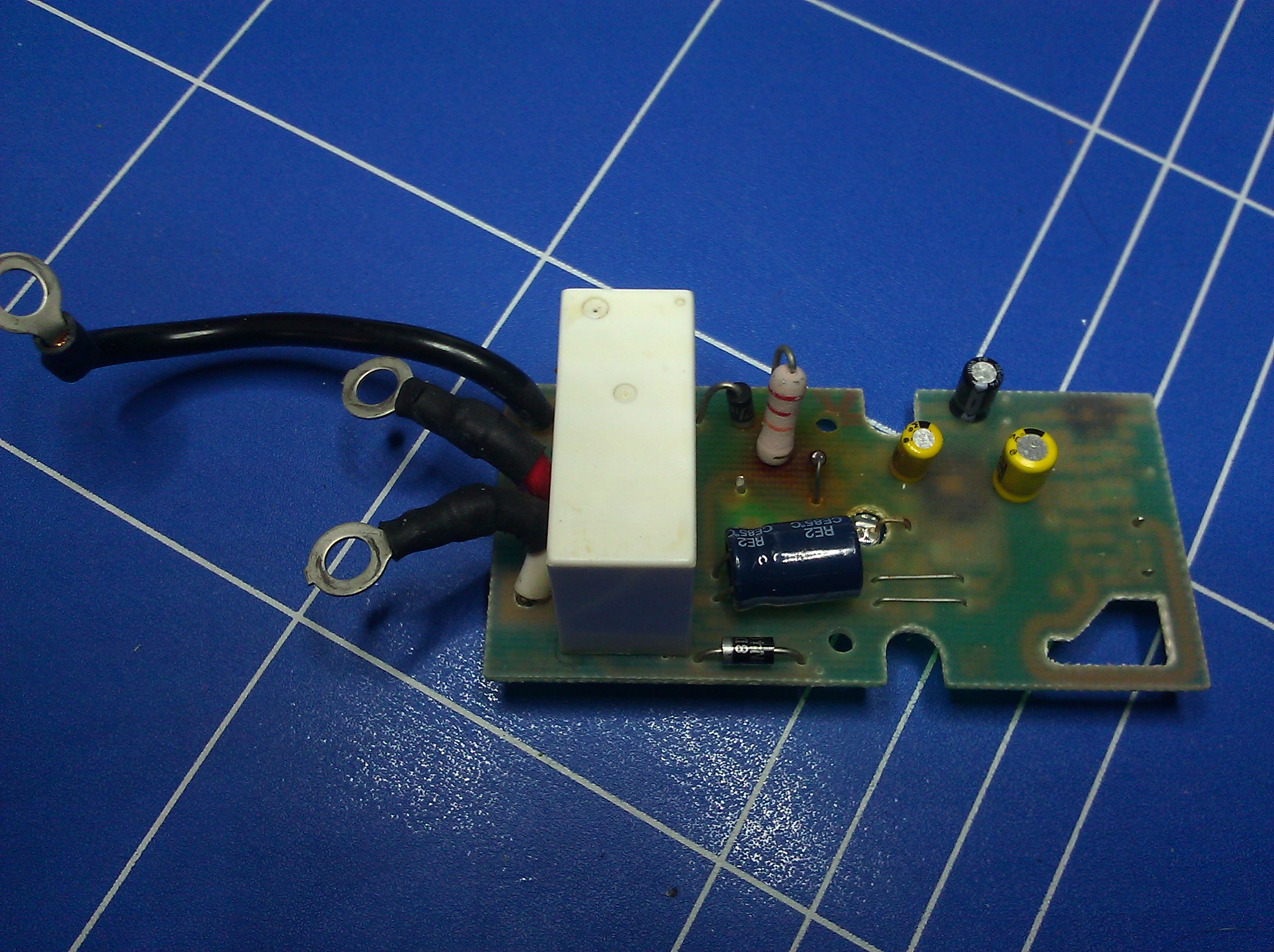
The disassembled remote and the original PCB. They use a 12V battery for the 434 MHz transmitter.

The first thing I did was to take measurements of the original PCB and transfer that to a simple Eagle layout. After quintuple checking the positions of every hole, notch, button and the LED I locked their positions so that I wouldn’t accidentally move them out of place later in the process.

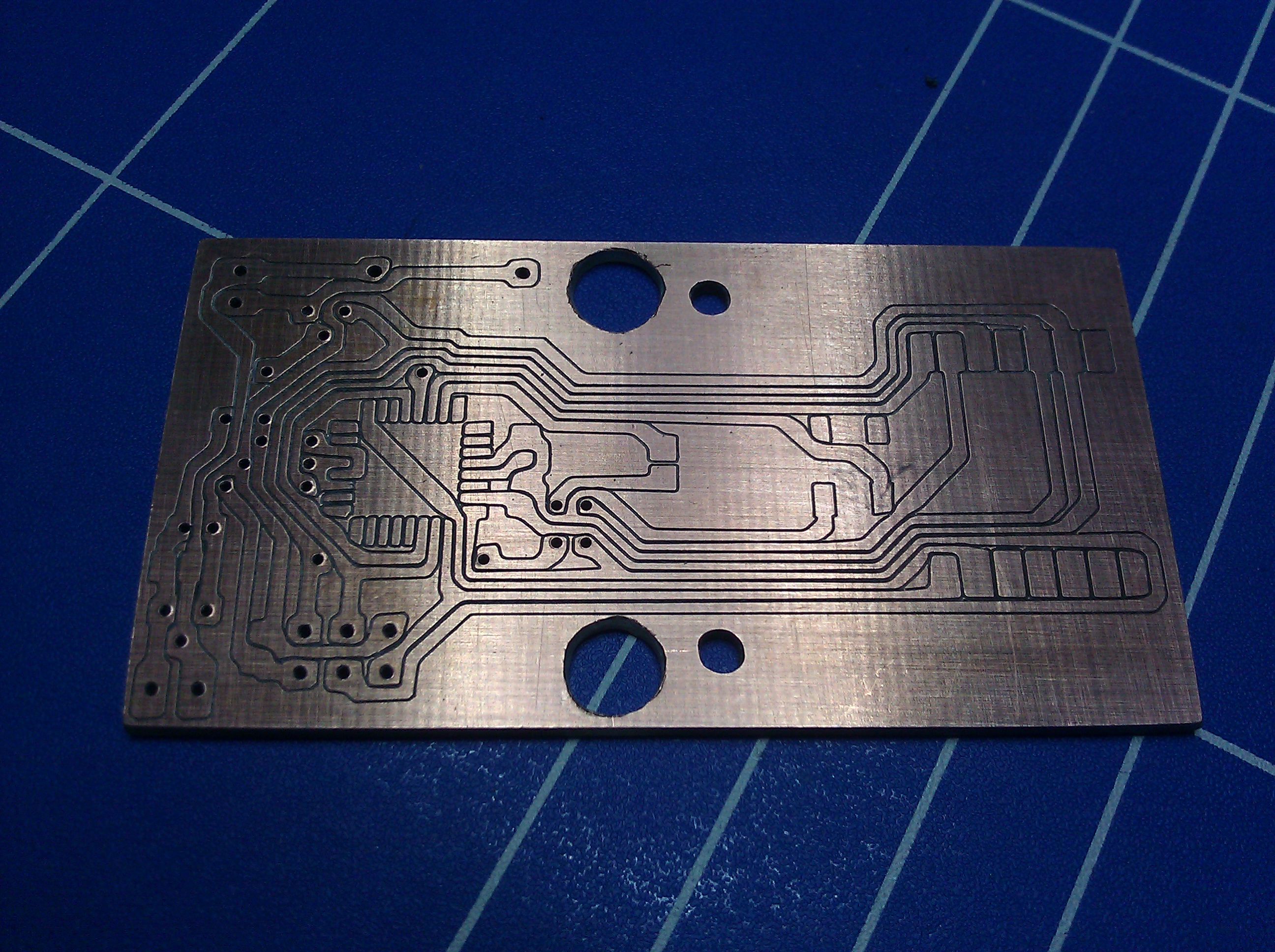
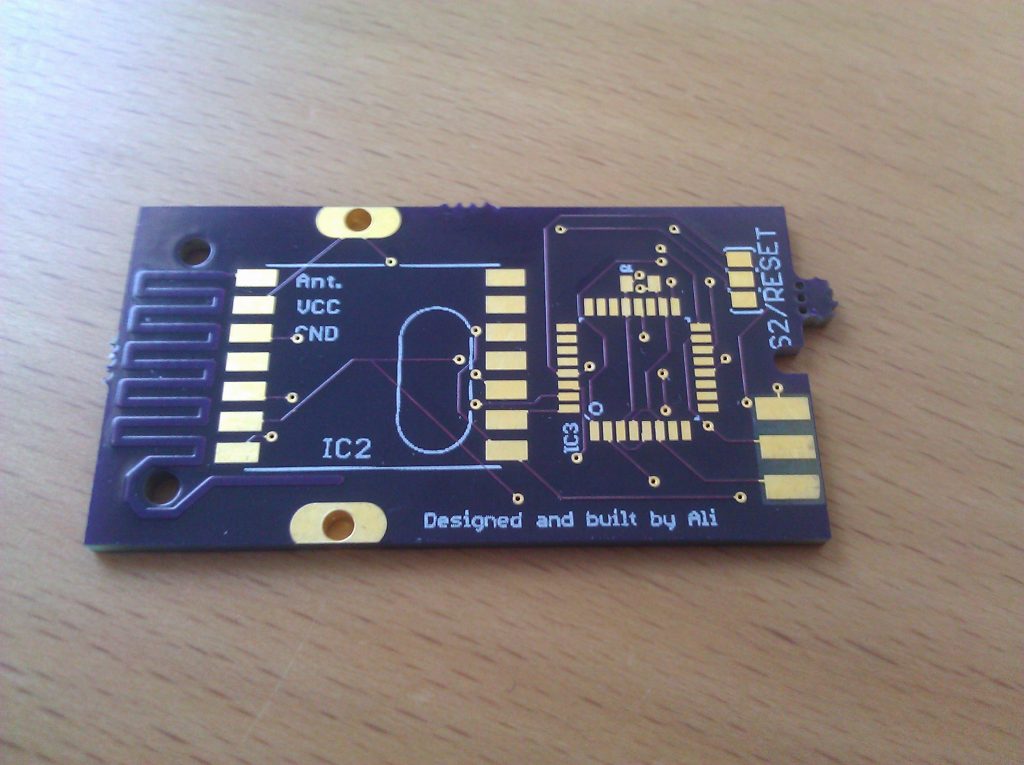
The back of the board on a scanner.
And the front. At first I tried to take measurements from the scan, but I soon realized I would have to get a caliper.

The problem with my layout was that it would not work with the kind of PCBs I could make on the CNC router at the Attraktor because the board would have to be double sided and I’ve tried to make a double sided board before and failed miserably. So I had to have the board for this project manufactured in a real fab house. The problem with that is that it’s really expensive for low volumes. If I had the board made on my own in Germany it would have cost me about $50. So that wasn’t an option.

By chance a friend told me about the dorkbot PCB-service (now called OSHPark). This is an extremely cool service run by a guy who started out collecting PCB layouts for his local hackerspace and put them all together on a big panel to reduce manufacturing cost. To fill up the panels quicker he opened his service to the public, so that is where I went.

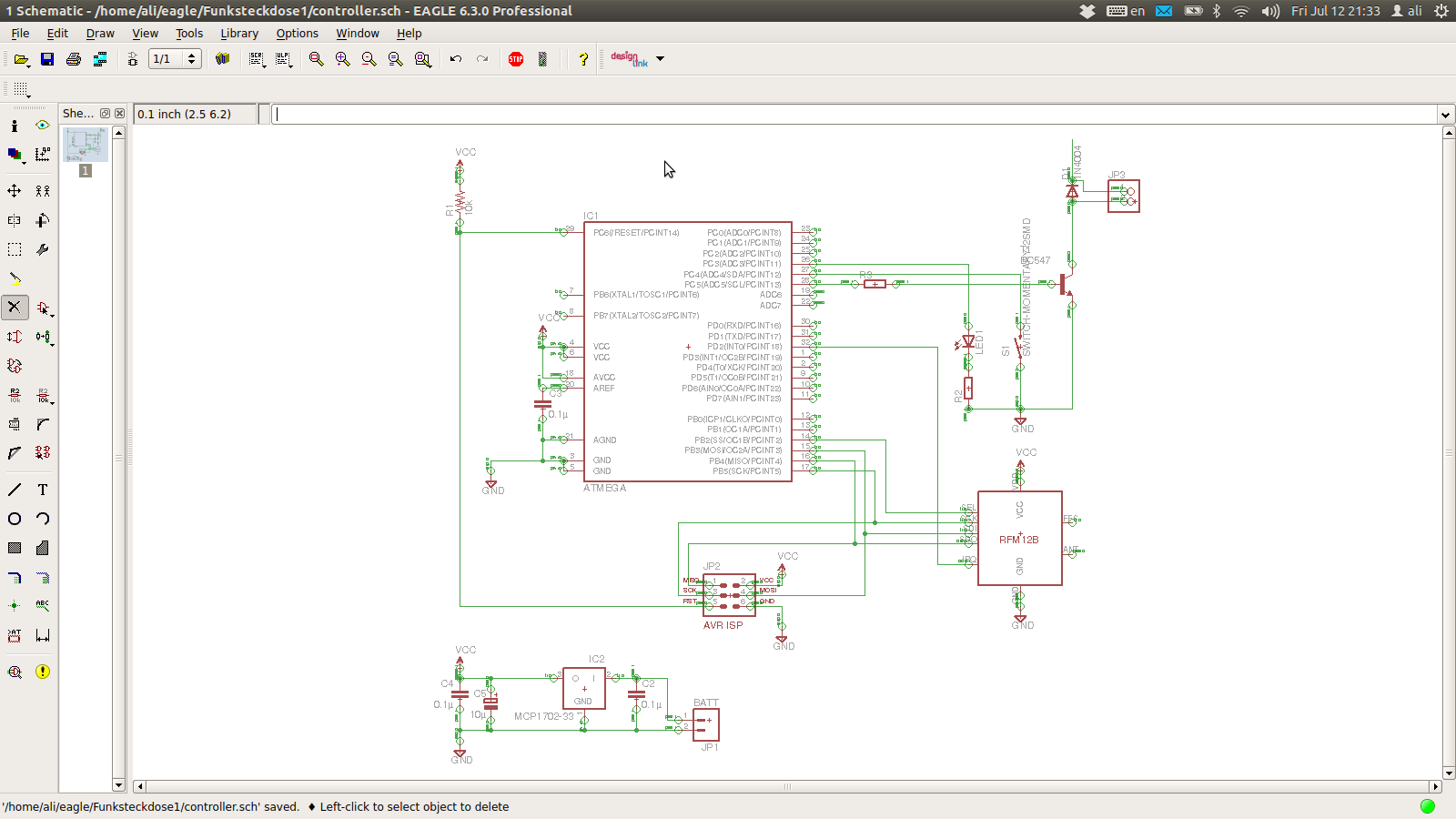
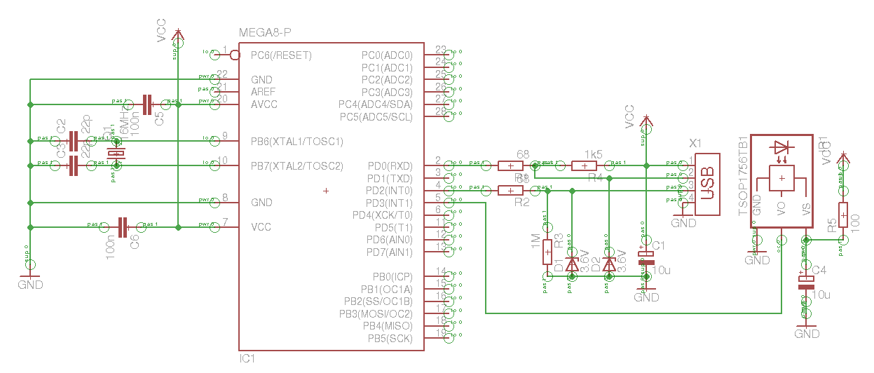
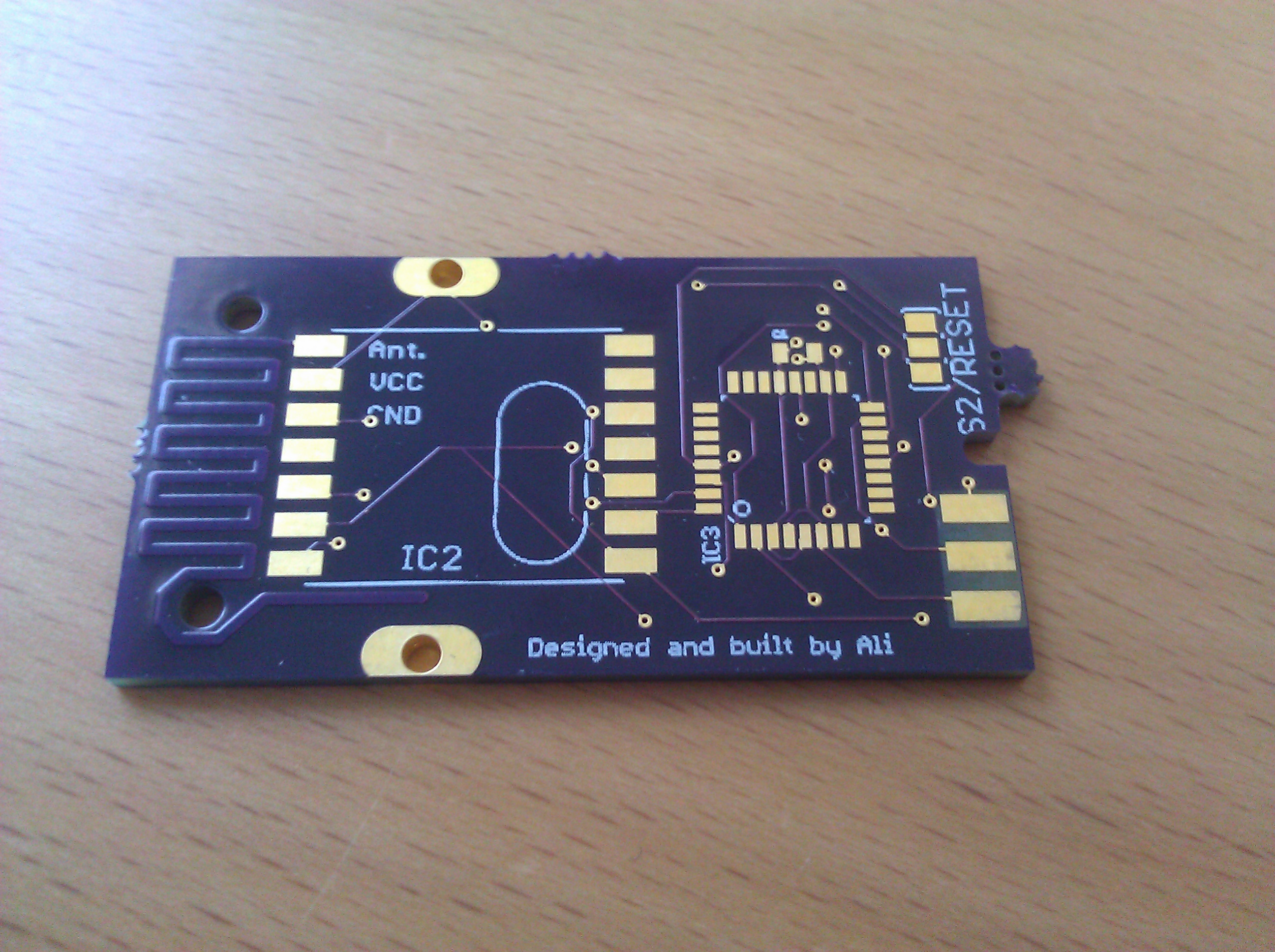
My Idea of a garage door remote in Eagle. Except for the antenna on the right I was really lazy and let Eagle autoroute most of the traces, which wasn’t too brilliant.

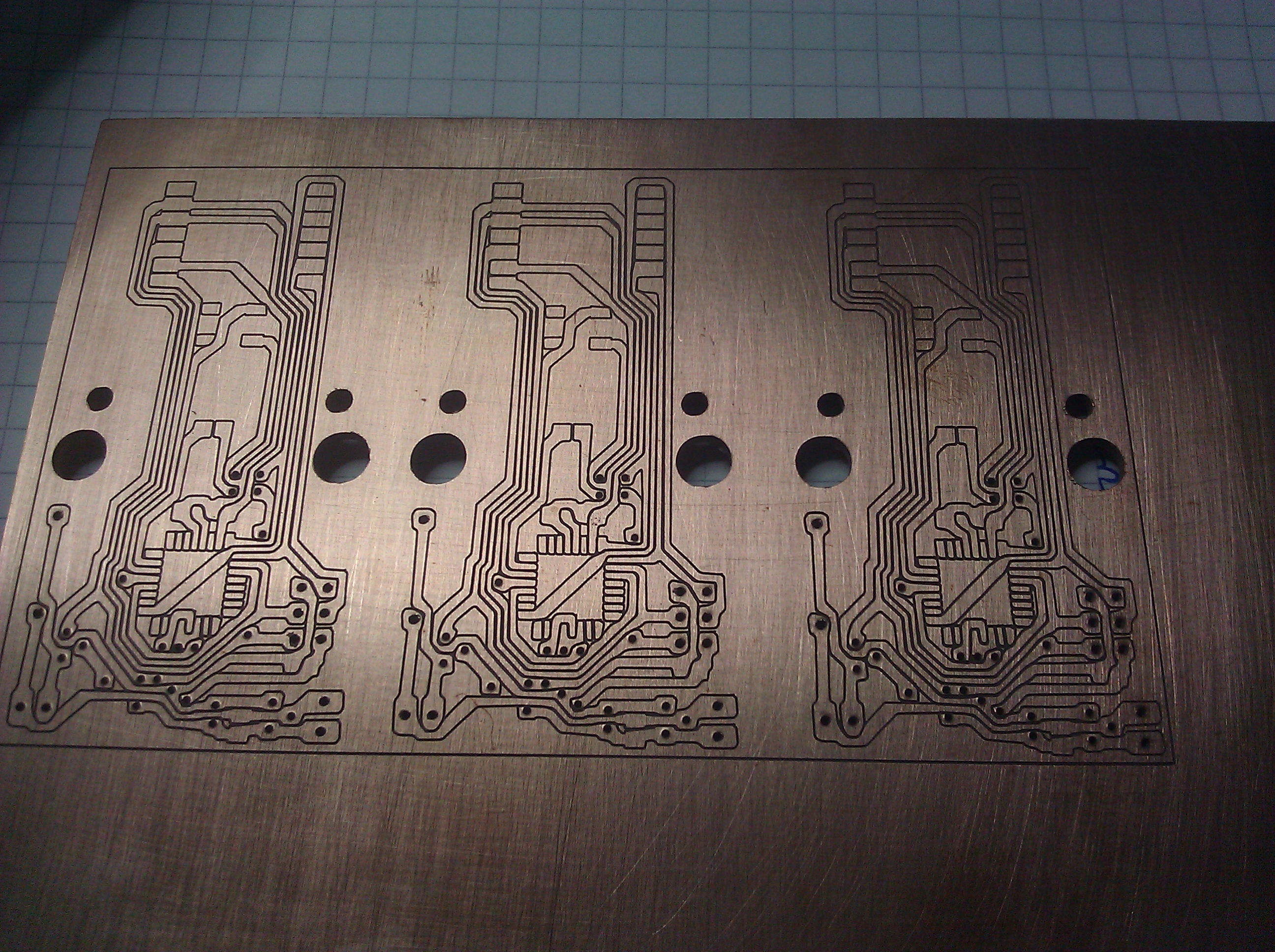
Having the boards made and shipping them across half the globe takes about 4-6 weeks, so after a long wait I finally had these in the mail:

I had round edges and a little notch on the “Dimension” layer. The notch is there but the round edges aren’t. I’ll have to remember to sort that out before I order the next batch.

And when I finally held them in my hands, it wasn’t long until I discovered the first fundamental design fault: There are a bunch of vias (gold plated, even!) right where the negative terminal of the battery would go. These I would have to insulate somehow.

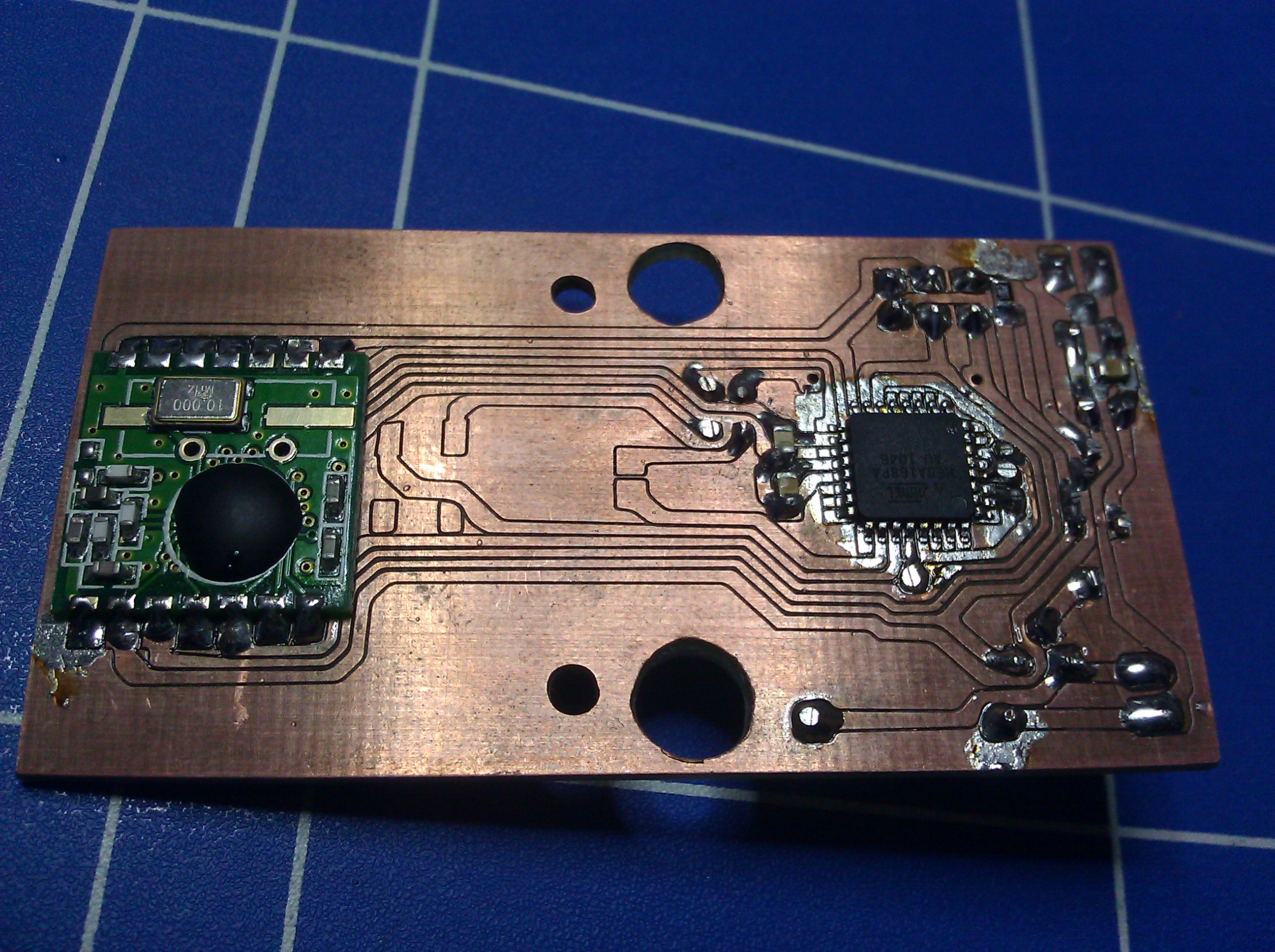
Later that night one of the boards looked like this:


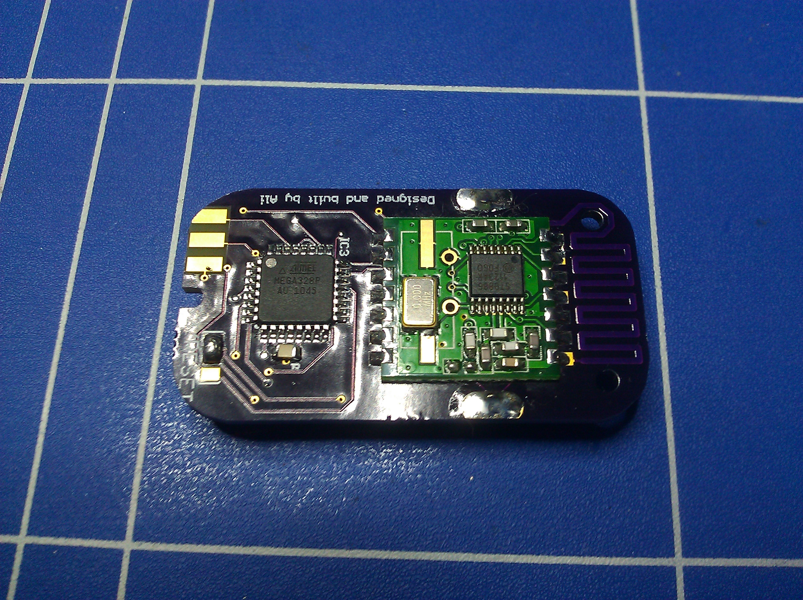
The ATMega is facing the wrong way. Ignore that.

I soldered the TQFP part using the solder wick technique shown at about 6:25 in this video (and probably many others).

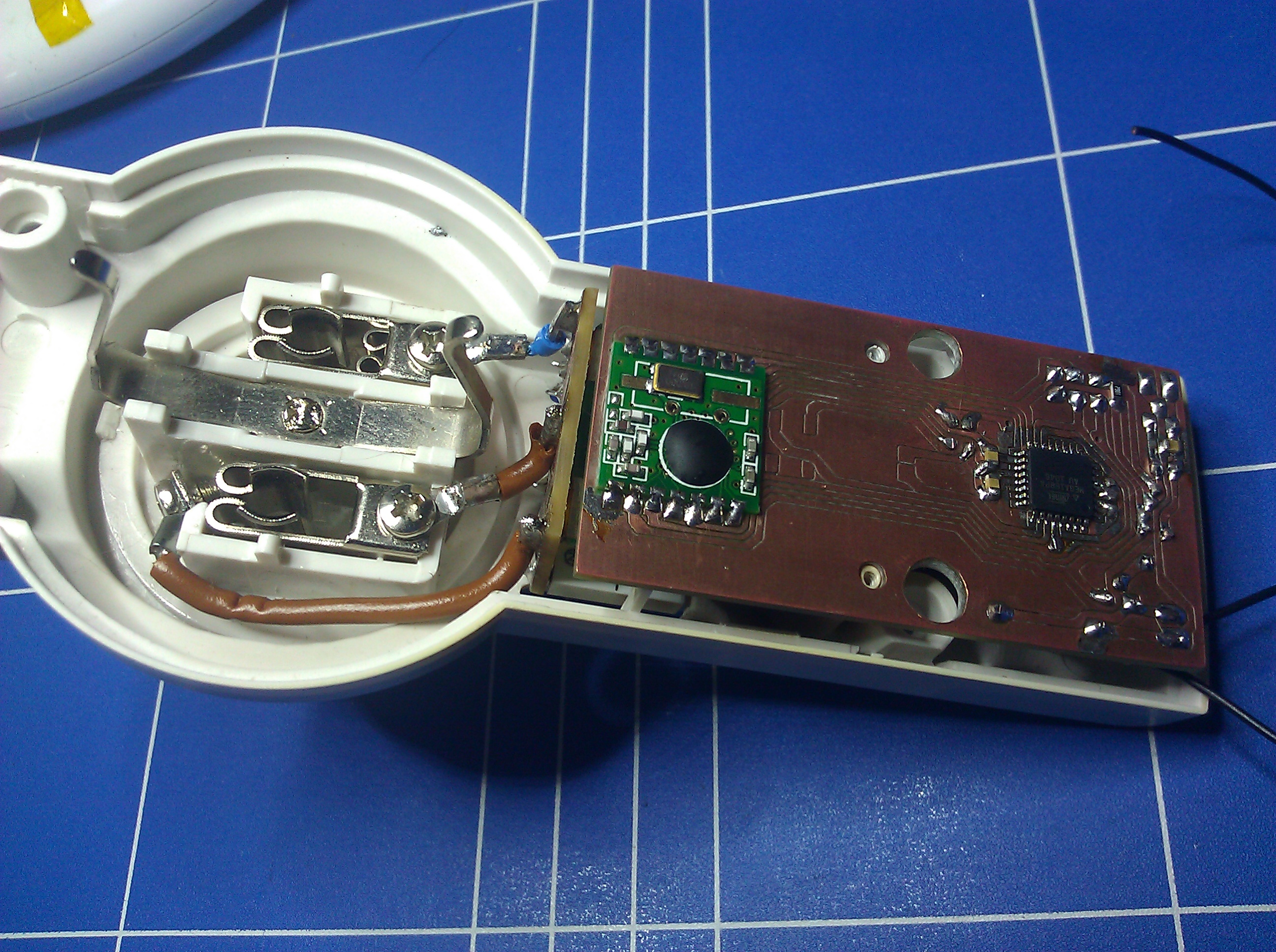
I left out the LED and the accompanying resistor on this board. Also note that I left out the notches on the sides of the board. I figured that it would be easier to just cut the enclosure to fit instead. Which worked.

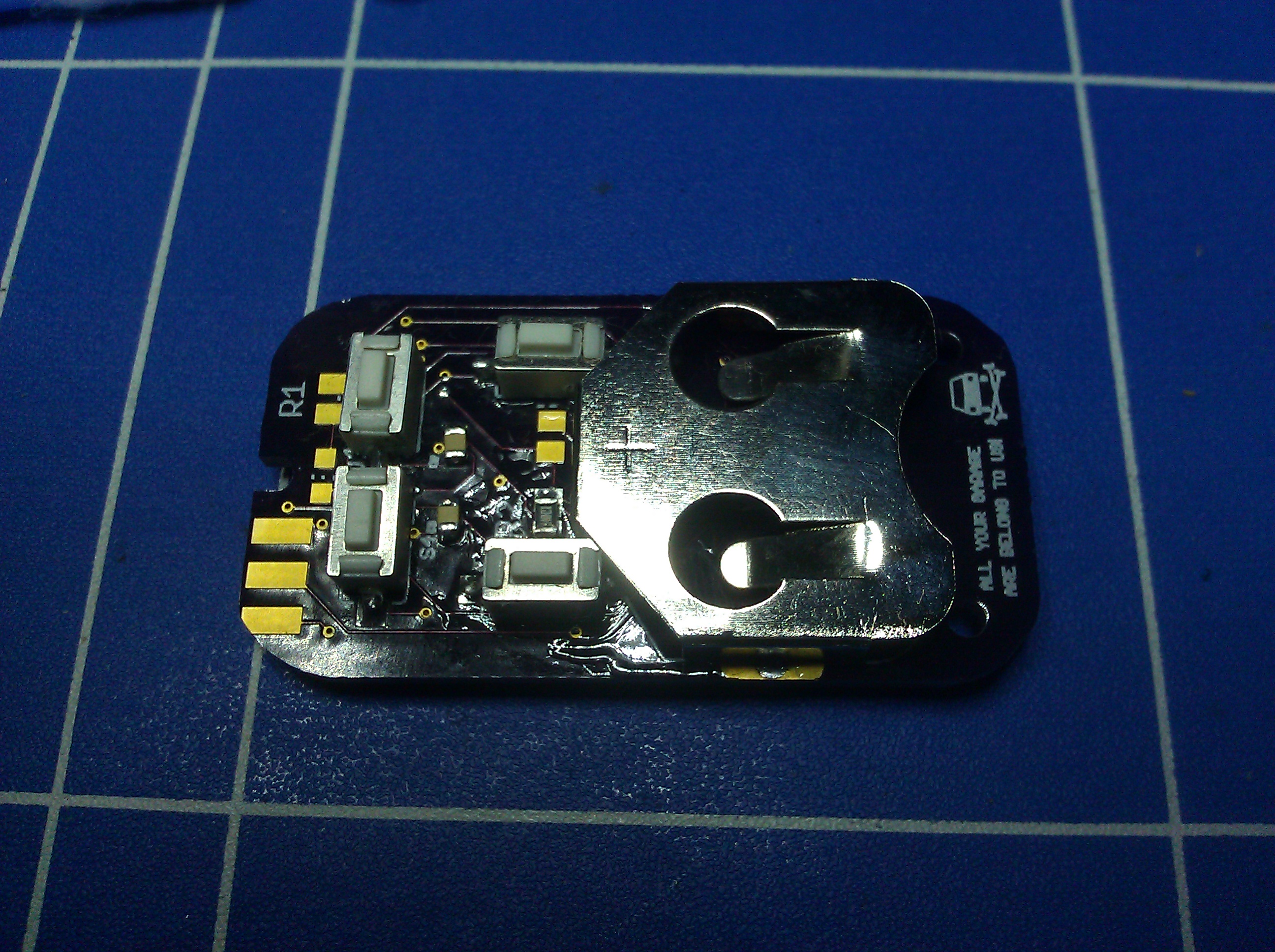
I insulated the vias under the battery clip with this stuff and I also put a lot of solder on the sqaure pad in the middle to raise its level above that of the vias.

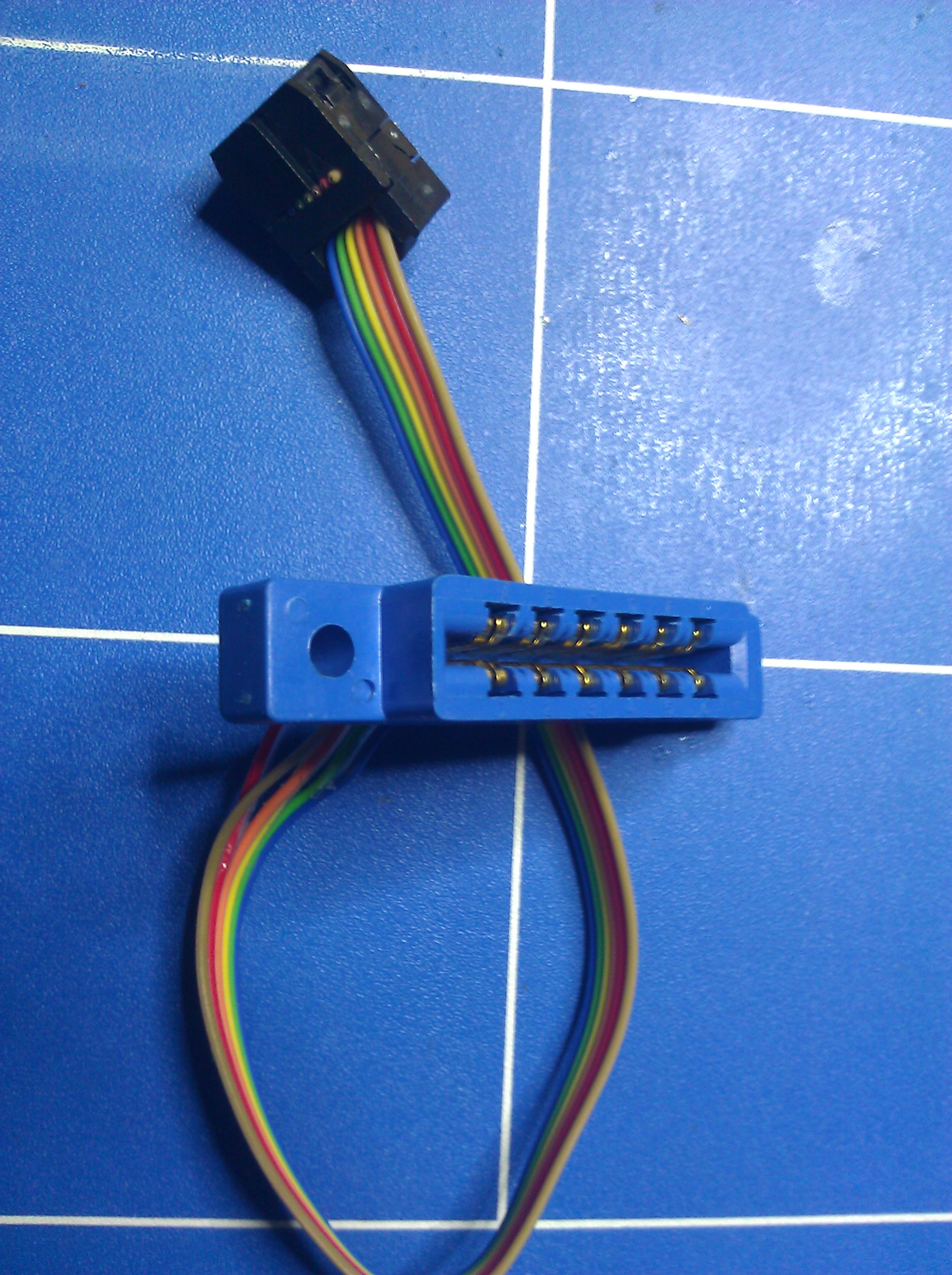
The ISP connector is done with the pads on the left. Now I had to find a connector to fit. A PCI connector should fit, or maybe an old floppy drive connector. Too bad I didn’t have any of those around. All I could find was an old connector for a C64 datasette port, if anyone still remembers those.

My barely working ISP Plug.

The pitch was totally off but it was the only thing I could find, so I used it. It was a royal pain in the ass but at least sometimes it worked.

Not that night, though… The programmer wouldn’t even find a controller to talk to. After checking all of the connections were good, I finally found it: The ATMega was facing the wrong way. Nice work.

De-soldering a TQFP part is no fun but it can be done. You have to add lots of solder, so that all pins are covered, and heat all four sides in a swift procession. The trick is to have the fourth side heated while the first is still hot. You’ll have to go around the chip for a few times but eventually it’ll come loose and you can just wipe it off the board. The major rule is: Patience > Violence.

After having this fixed I could flash the controller but the damn thing still wouldn’t work. I had to get out the logic analyzer. Luckily the connection between the ATMega and the RFM12B is an SPI connection, which is basically the same as the ISP connection for the programmer, and it also uses the same pins (mostly). So I could connect all but one of the analyzer probes to the programming connector. With help of the analyzer I could see that the controller was talking to the RFM12B on the MOSI line but wasn’t getting an answer on the MISO line. This meant that the RFM12B wasn’t working properly for whatever reason, most probably a short circuit somewhere on the board.

After poking around with the multimeter for another while I found it. Or, more precisely, I found out which nets were shorted out, but I had no idea where.

By now I had a little practice in de-soldering larger SMD parts, but even after removing the ATMega and the RFM12B (the de-soldering trick described for the ATMega works with that, too), the short was still there. It was between the SEL signal of the RFM12B and VCC, i.e. the positive terminal of the battery. But since these two nets virtually never cross paths or even come close to one another it had to be somewhere else. And here it was:

The SEL trace of the RFM12B crossing the drawing of the battery clip on the “Dimension” layer. Looks perfectly innocent in Eagle.

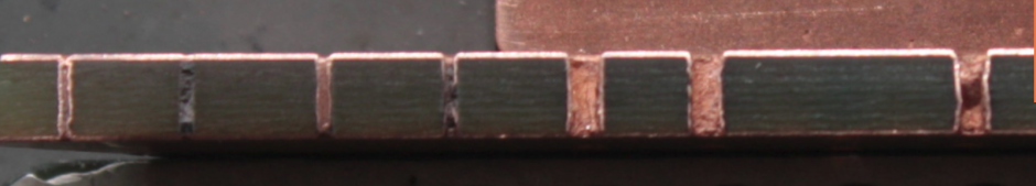
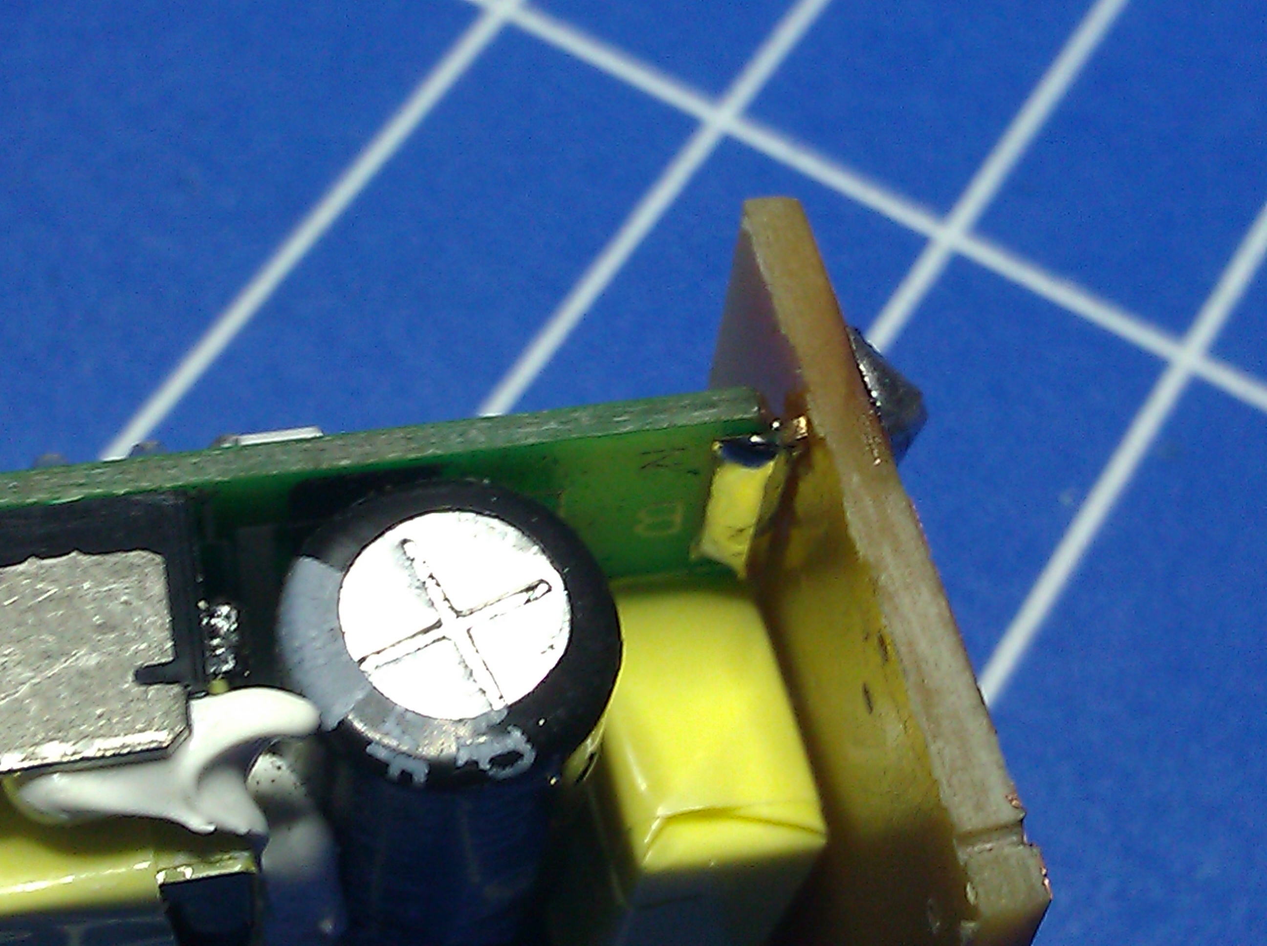
This is what it looks like in real life:

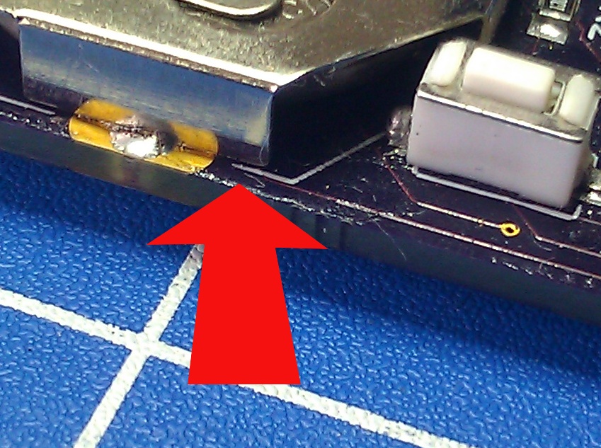
Not so much in real life. The metal of the battery clip cut through the soldermask somehow and shorted out VCC with SEL.

After gently bending the battery clip everything worked like a charm. Well, at least the hardware did.

The software:
The PoC didn’t have a real program logic at all. As soon as you connected the power, it would transmit away. For this project I wanted something slightly more elegant. In addition to just sending the garage opening signal, the buttons should send something I could use around the house, like a unique ID, that I could process in projects to come. Also I had to do something about the current consumption. Both, the ATMega328p and the RFM12B have ultra low power sleep modes and I needed to utilize those to make the coin cell last more than a few hours. Again I had lots of help from the internets, particularly here and here somewhere near the bottom. After some tweaking I had the standby power consumption down to under 1 µA.

At this point I’d like to praise the Internet. I couldn’t do shit without it.
The only problem with the code was that it wasn’t very stable, and I couldn’t really fix that.

(The PCB design actually reflects how little trust I had in my own coding skills: I put in a little solder jumper to be able to use one of the keys as a reset button for the AVR. But that was planned as a last resort in case I really couldn’t get the code to run properly.)

Luckily, for cases just like this, the ATMega (and probably other microcontrollers as well) has a watchdog timer, that will reset the whole controller if you don’t reset the timer before it runs out. After implementing that, everything is running smoothly for several days now.

Conclusion:
I’ve learned quite a few things about PCB design doing this project:

  • Don’t trust the autorouter of your PCB design software. Better yet, on a project as simple as this, don’t even use it.
  • Think 3D! It’s hard to imagine a
    real life PCB just from an Eagle layout. There are 3D rendering plugins for Eagle and other software with this functionality built in, but I found it the easiest to just print out the PCB layout on a piece of paper and place the parts on it.
  • Only use parts in your design that are actually available to you. I have  yet to find a correctly pitched edge connector for the ISP connection.

Total cost of the project:

  • PCB: 3.30 €
  • ATMega328p: 1.80 €
  • RFM12B: 4.00 €
  • Chinese fake-cloning-remote: 2.50 €

Makes a total of 11.60 € or US $ 14.35 at the time of writing. All prices include tax and shipping and all items were purchased in low volumes.

Files:
All design files as well as the source code for the controller are available at my github repository:

Update:
As it turned out, the watchdog timer (or rather the way I implemented it) didn’t really help, actually it made matters worse! After a long and tedious debugging process I finally think I’ve got it right. Read about it here.

Posted in 868MHz, AVR, Digital, Wireless | 9 Comments