I hate tinkering with AC mains. But if you want to get “real” things done around the house there is no way around it. So before this goes any further, here is the disclaimer:
AC mains power is dangerous. It can kill you and/or burn your house down if you are not careful. Unless you know exactly what you are doing, DON’T TRY THIS AT HOME!
That being said, AC mains is no rocket surgery either and probably no one in their right mind would call a union electrician to hook up a lamp.
So, what is there to switching mains? Not much, actually, it’s just a sufficiently rated relay to switch the hot or neutral wire (it doesn’t matter which, either will break the circuit and prevent current from flowing).
There is a variety of readily made hardware available that will accomplish this but from my point of view all these products are flawed: The ones that work reliably are expensive and the cheap ones are unreliable.
Hardware:
I had a few very cheap and extremely unreliable ones around, so the obvious solution was to gut them and use the enclosures for my own design.
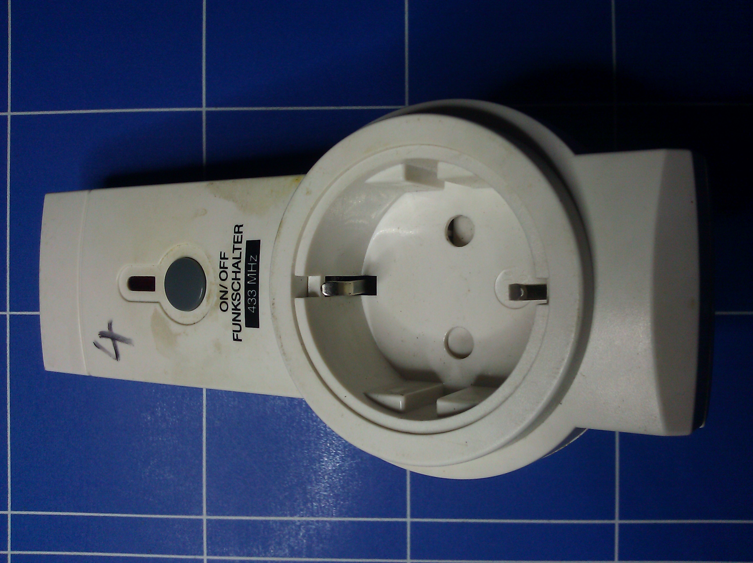 |
| I got these about 20 years back, as you can tell by the grime.. The set of four was about 30 DM, back in the day. |
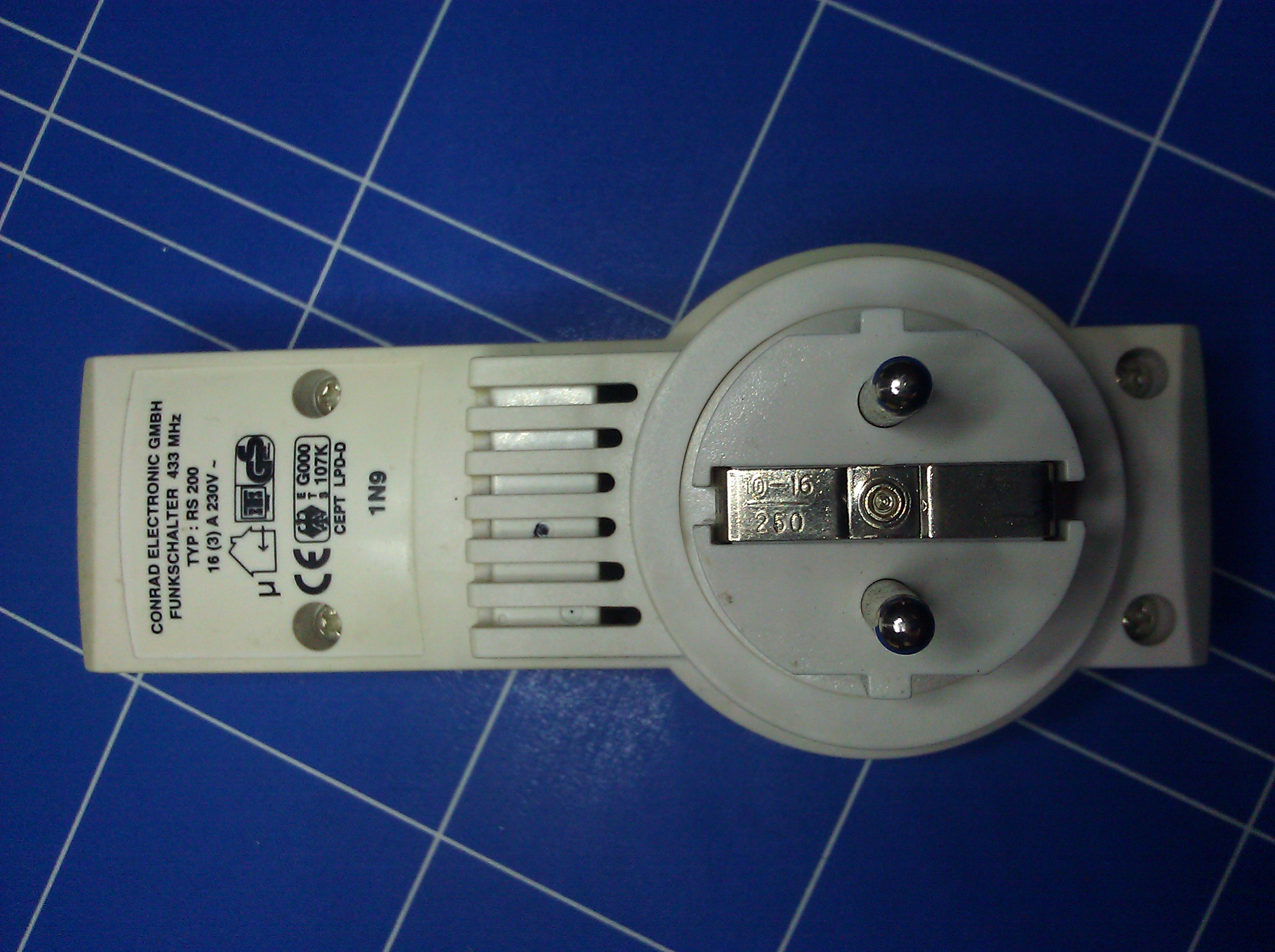 |
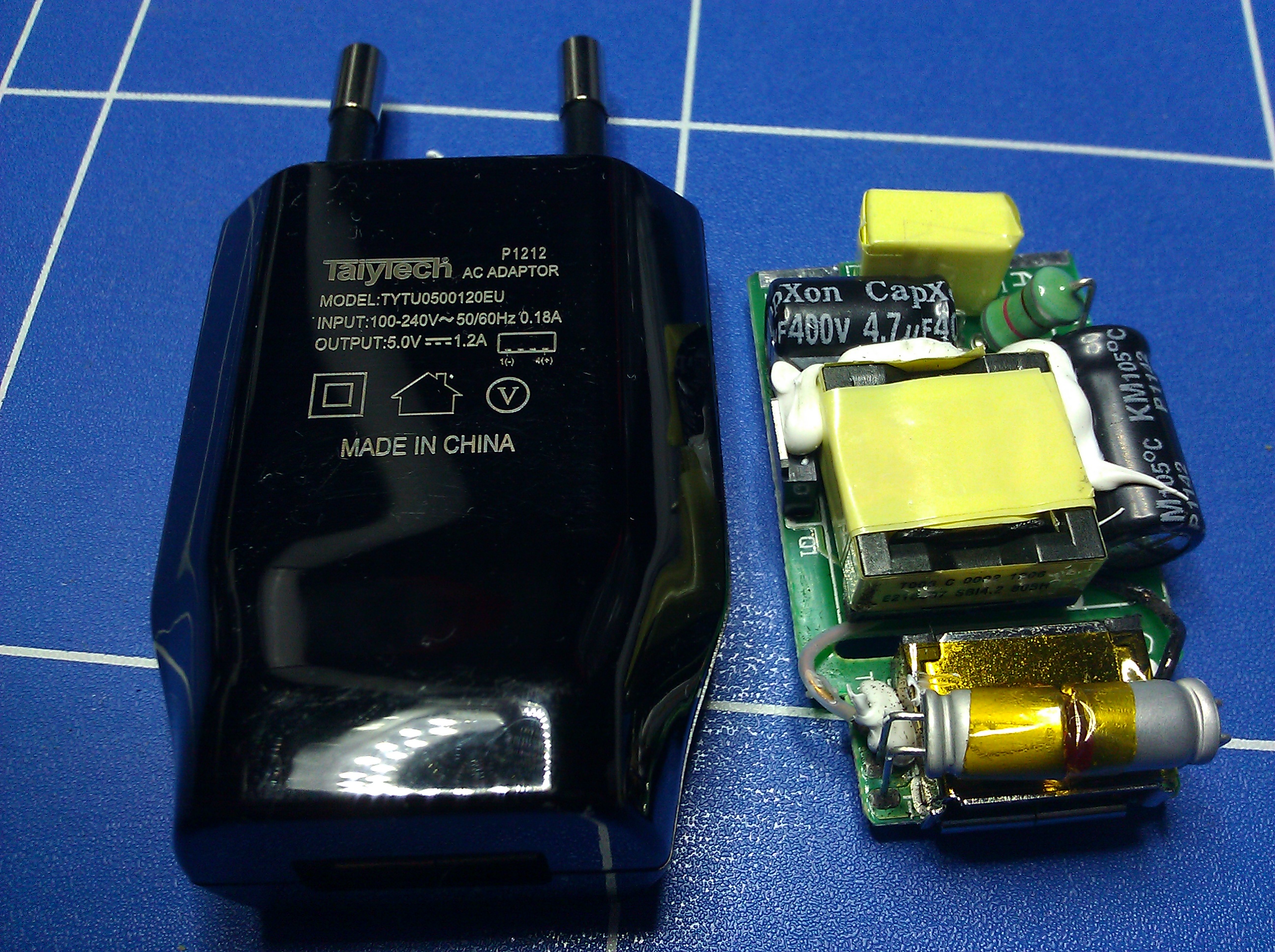
| All those certifications… Must be good stuff inside… |
 |
| The enclosure looks quite nicely engineered. But what is it with that crappy and kind of burned looking circuit board? |
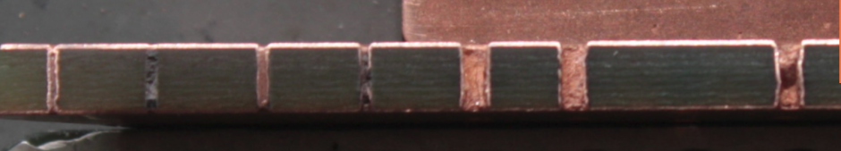
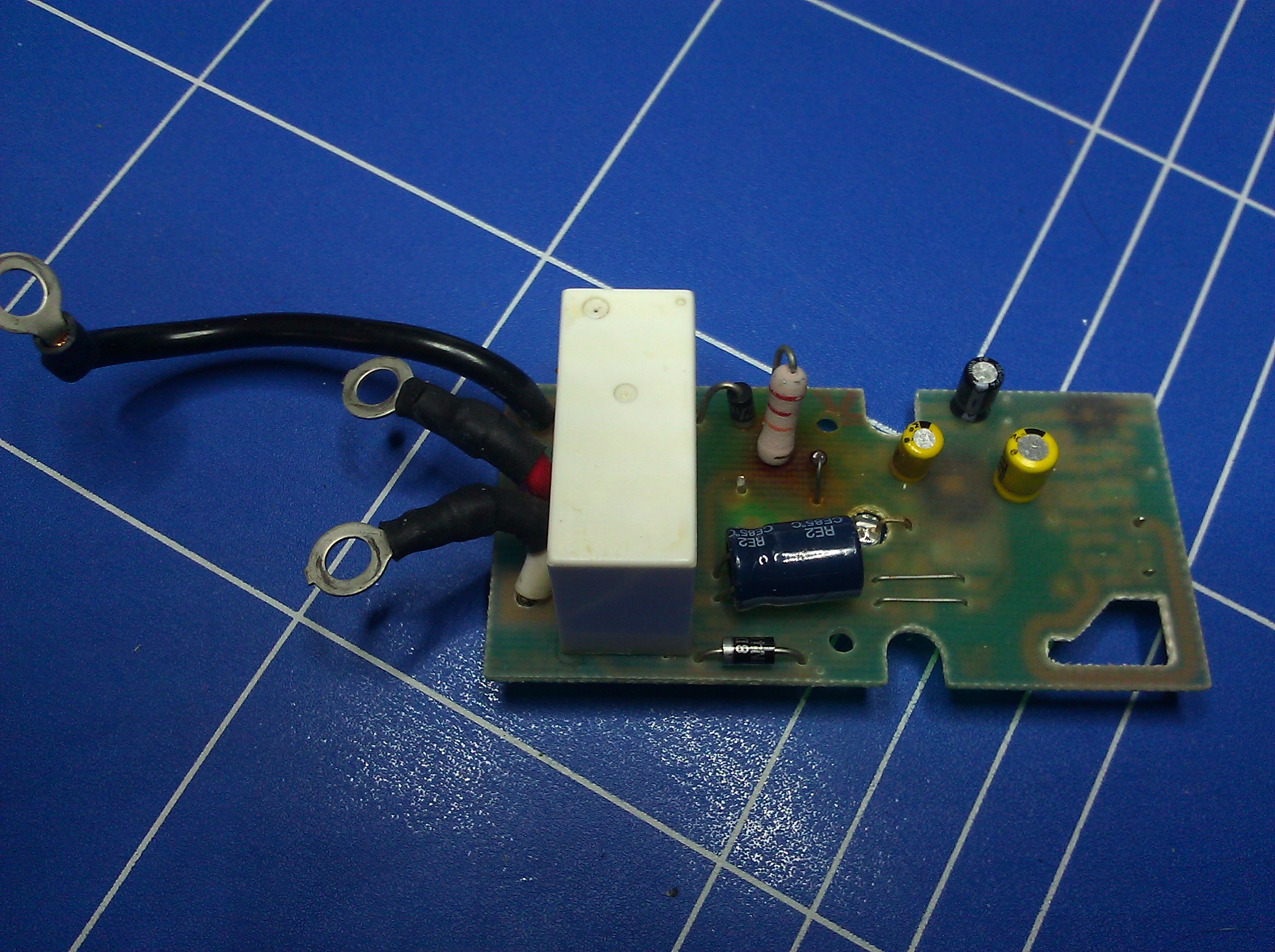 |
| Yuck! This isn’t even a cap dropper, this is basically just a resistor on a mains wire, and it looks fried up pretty good. How did they get all those safety stickers with this? |
The design itself is simple: Just hook up a relay to an Atmega with an RFM12B. If there wasn’t the issue of a power supply. Looking at commercially available solutions there seem to be mainly two options: Go with a full blown switch mode power supply or implement some sort of ultra cheap non isolated cap dropper type power supply. Both have a list of pros and cons:
SMPS pros:
- isolated from mains
- efficiency
- size
- price
- size
- price
- not isolated from mains
- inefficiency
 |
| These are really nice. But also very expensive |
There are SMPS-Modules that would be ideal for this project, but unfortunately those cost about 30 € a piece, which is about three times of what I intended to be the cost of a completed socket, so those are out.
 |
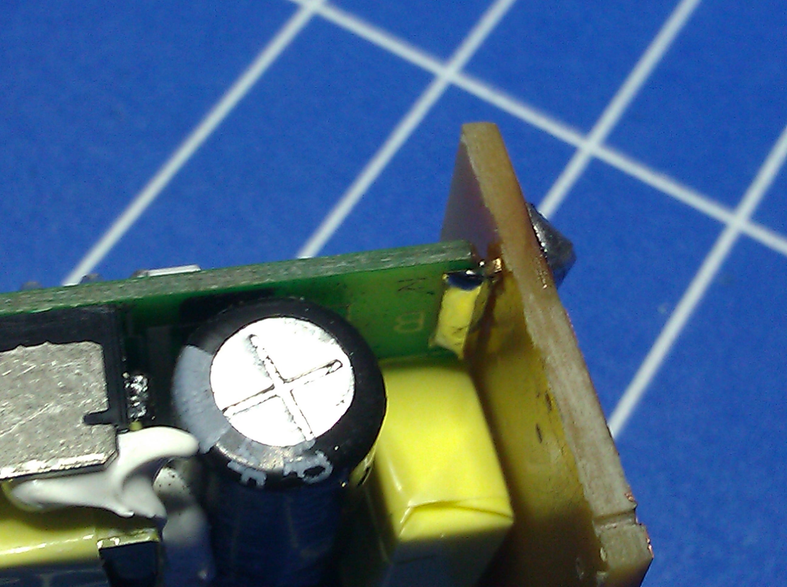
| The switching transistor bent over to the secondary side was the reason this one was rejected |
 |
| Almost as tiny as the “Apple” chargers |
It’s cheap, small and at first sight not too dangerous. At least there were no reviews about these things blowing up all the time.
 |
| This looks more like it. A nice big slot between primary and secondary side and no parts hanging over from the dangerous side. |
With this out of the way I was finally set to go. To make the PSU fit the enclosure I hat to cut it along the slot that was already there.
 |
| Nice fit. The mains side of the PSU is on the left |
Space was an issue with this project. I could have easily thrown those old sockets out and gotten new ones with bigger enclosures, but where would be the fun in that?
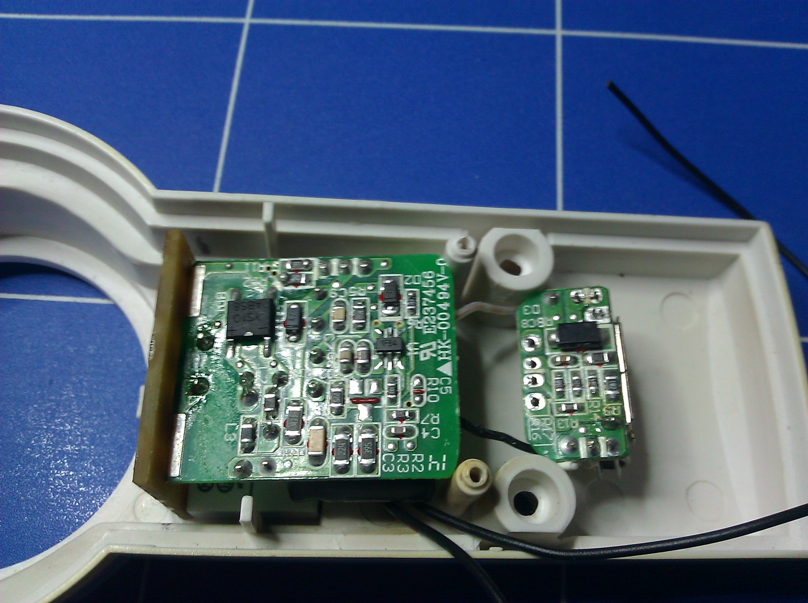
So, after I pulled out that deathtrap load of crap PCB I found inside, I went through the usual process of measuring the enclosure and designing a new board in Eagle.
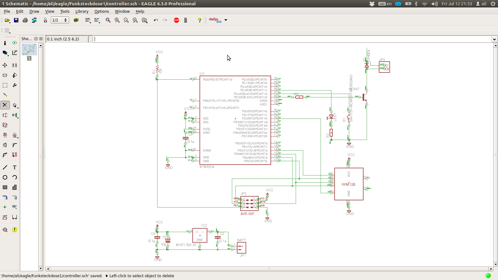 |
| Boring. |
 |
| Also quite boring. This is hand routed, and I needed six jumpers. Lame. |
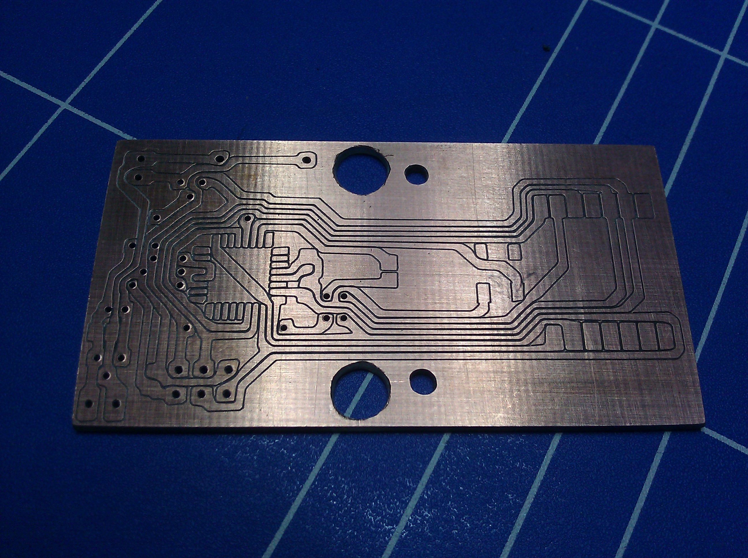
To accommodate the PSU, the relay and my controller board I had to make two PCBs: One for the controller and RFM12B, the “cold board”, and one for the relay and the PSU, the “hot board”.
 |
| The “hot board”. This will only contain the relay and mains connections for the PSU. This isn’t its final form. The leftover copper at the lower edge of the board was of course removed. At the left lower edge I hat already removed a bit too much. |
 |
| To connect the PSU to my adapter board, I just bent two regular pin headers and soldered the PSU’s mains contacts to them. |
 |
| The “cold board”: This will contain the RFM12B and the Atmega |
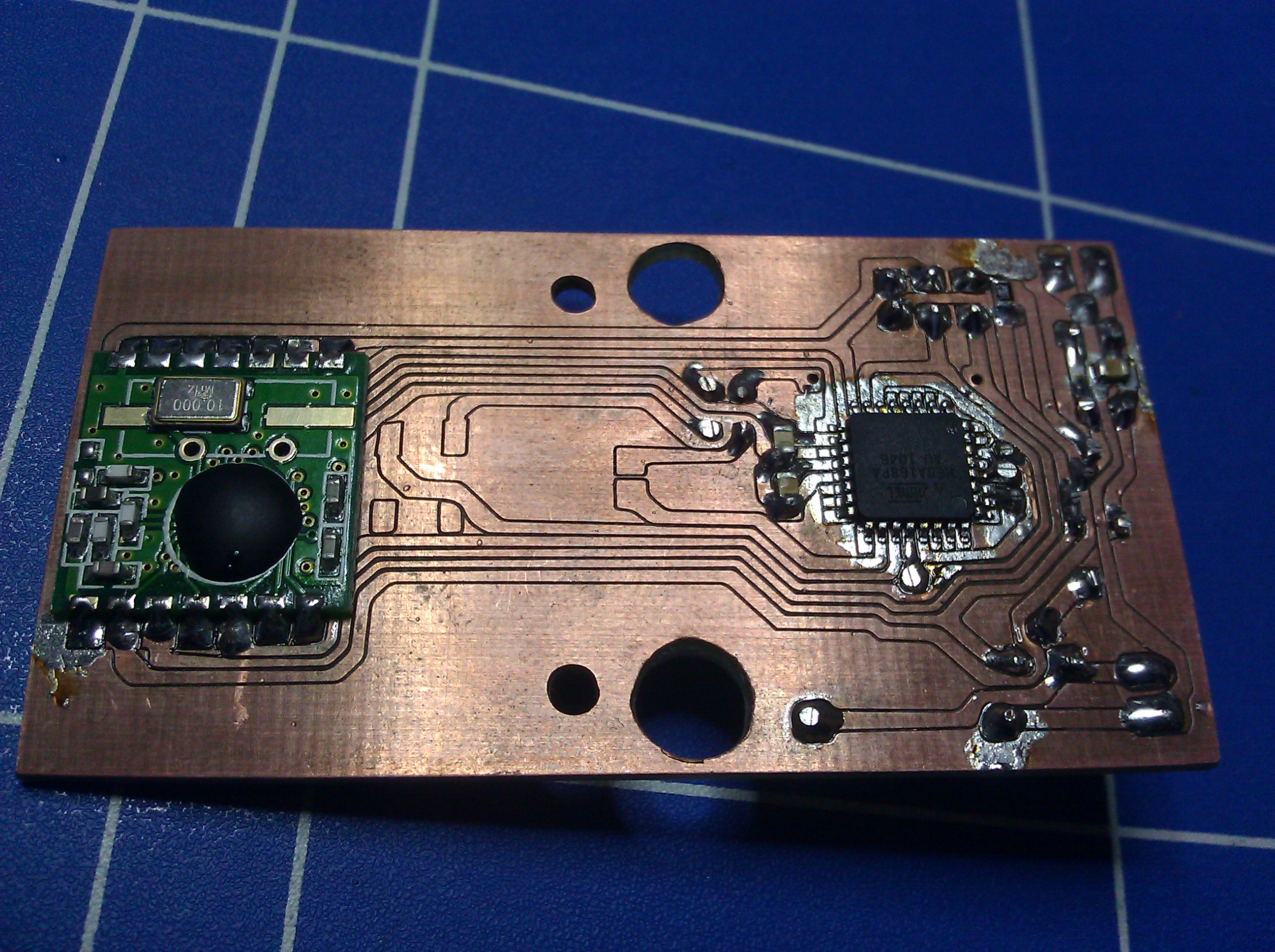 |
| The push button and the LED are still missing. |
 |
| Note the absence of parts on the right hand side of the board. That will be on top of the mains side of the power supply. |
The controller board would be on top of the PSU. To eliminate the risks of accidentally shorting anything to the mains side of the PSU I arranged all
parts on the controller board so they would be a safe distance from all the scary mains stuff.
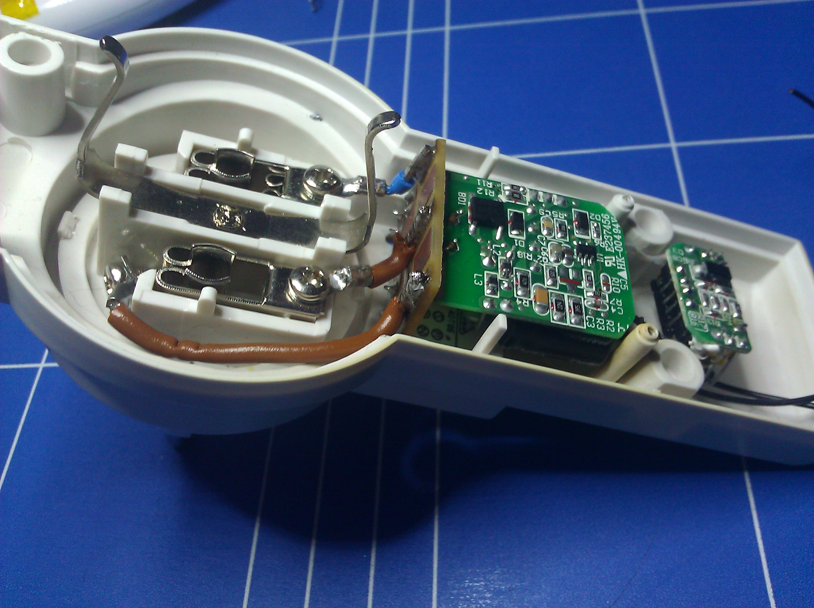 |
| The hard part is done. Those heavy duty mains wires weren’t too much fun to work with. |
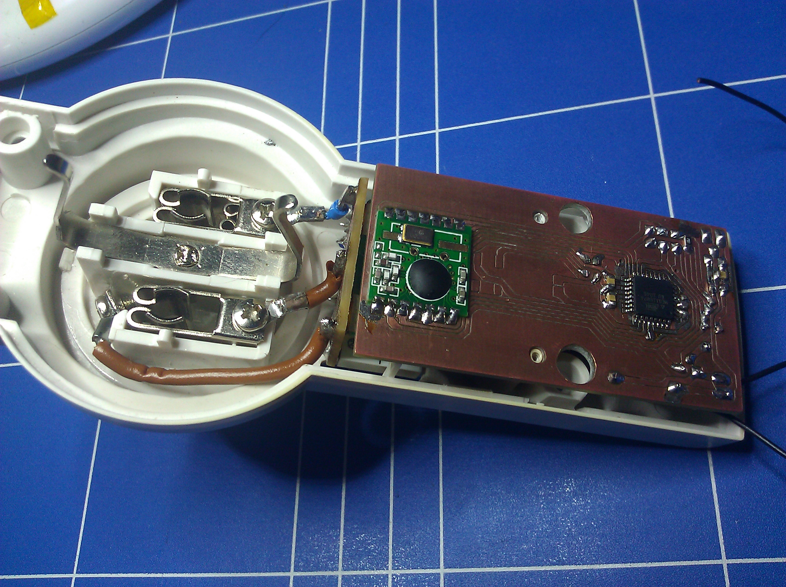 |
| Almost completed. Now only the wires from the PSU and to the relay need to be connected. |
The prototype worked perfectly, so I was ready to go into production…
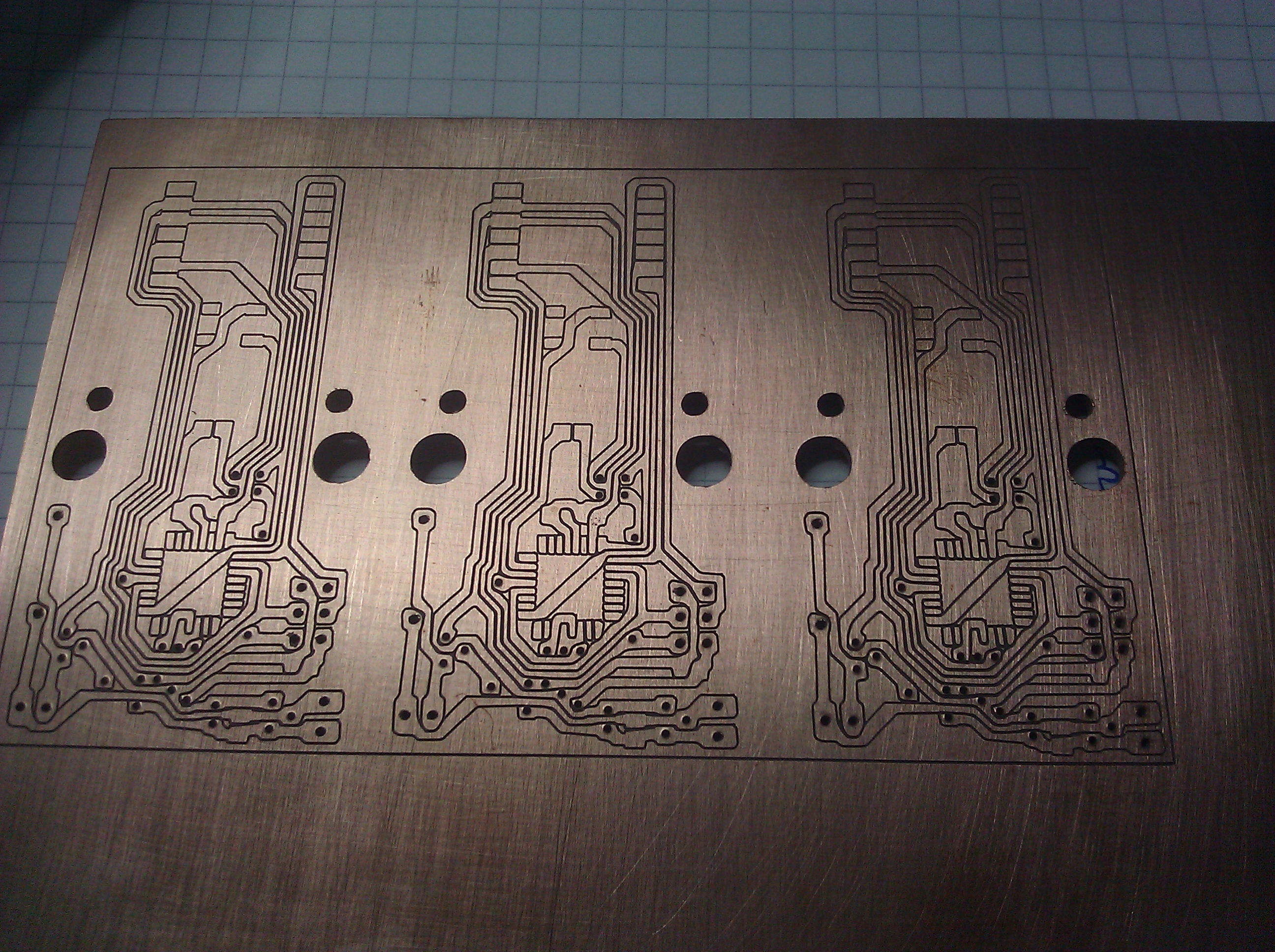 |
| Three more controller boards. I was smart enough to put three boards on a panel, but not to think about routing the outlines of the boards. m( |
 |
| …and the PSU/relay boards. |
There was some time between building the first prototype and finishing the rest of the bunch, so it slipped my mind, that I used a m168p on the prototype and m328ps on the other three, but it wouldn’t have changed anything, because I hat no 168s left. Well, now I have to have a type A and a type B in my Makefile. Never mind.
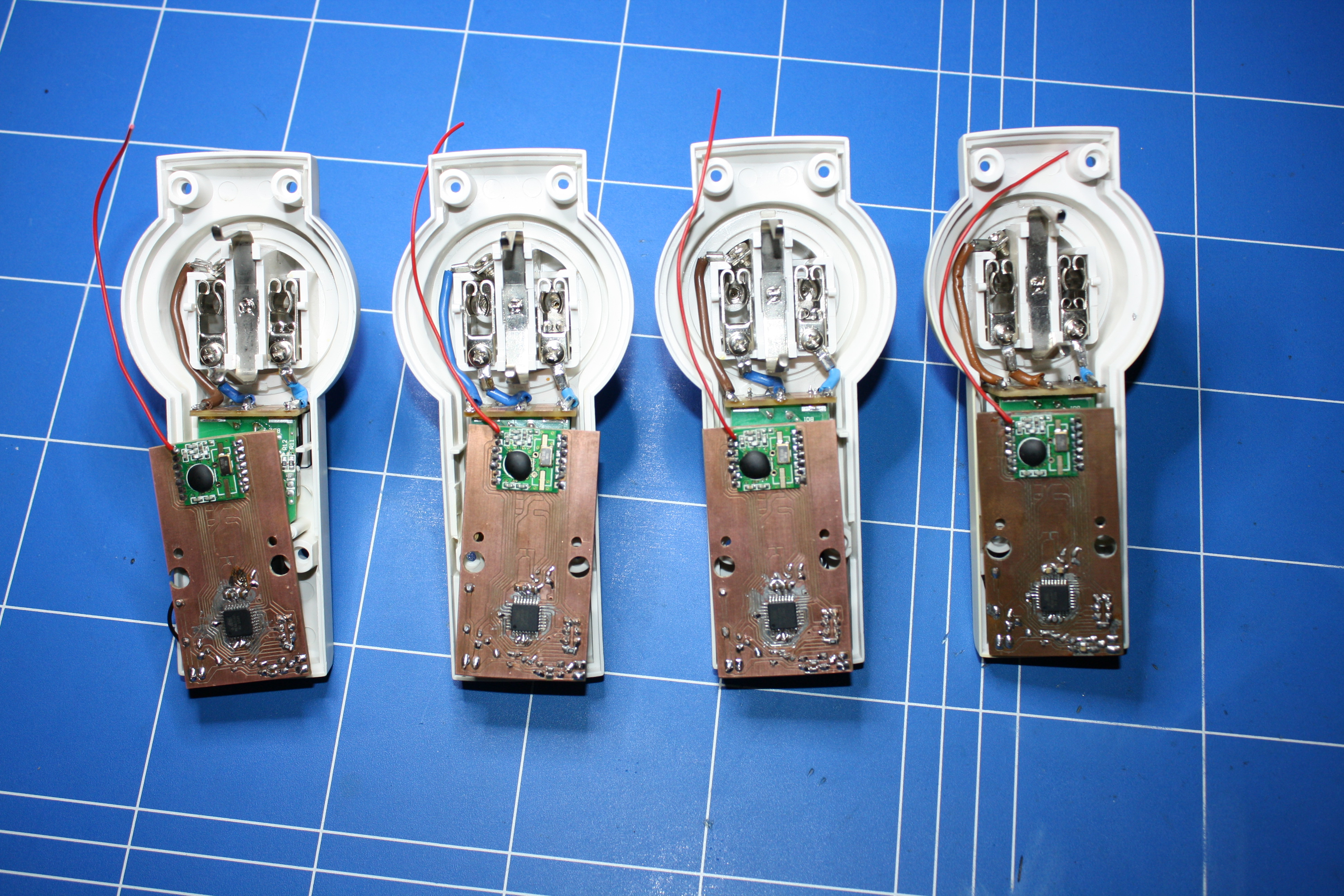 |
| The semi finished sockets on the “assembly line”. |
They work beautifully and the power supplies are quite efficient. With the relay idle they draw about 0.2W and with the relay active it’s about 0.6W. I vaguely remember, that the original circuit drew about 2.5W, no matter what. I could maybe reduce the active power consumption another bit by driving the relays with PWM, since they need a lot less power maintaining an active state than switching to it, but that’s for another day.
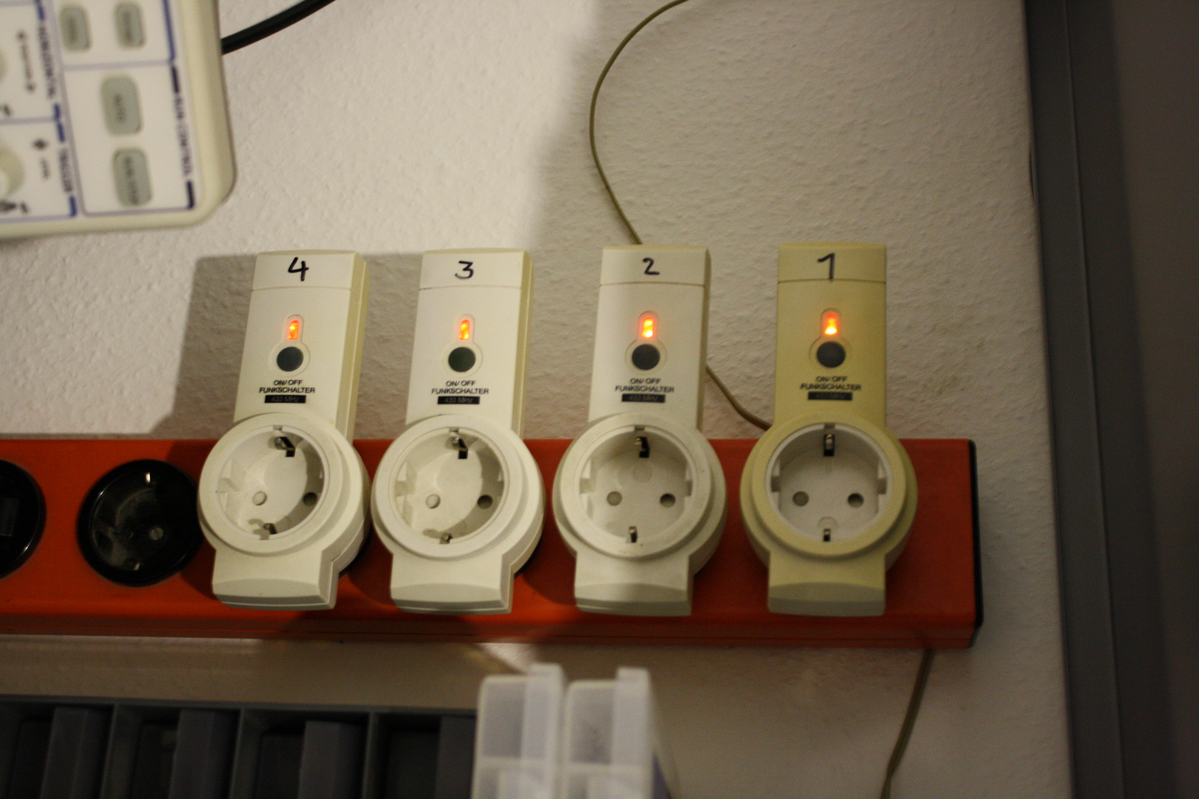 |
| I finally got around to adding the LEDs. The buttons are still missing, though. |
Software:
On the code side there are a few things to mention:
The sockets tie into my sensor and home automation infrastructure, I have yet to write a post about. Basically every type of device uses a separate rf12 node id, which is shared among all devices of that type, which in turn all have their own individual mcu ids, which are stored in eeprom and can be set dynamically.
When a virgin socket is powered up for the first time its mcu id will be 0xFF, because that’s the default value of untouched eeprom. If the id is 0xFF, the controller will go into a loop where it sends a packet every second announcing that its id is unset. In this mode the only command it accepts is one that assigns it an mcu id, which is then written to eeprom.
With the mcu id set, the controller will enter its normal mode in which it will listen for packets with matching node- and mcu id and do what it’s told. In this mode the relay can be turned on and off or queried for status.
Conclusion:
This was a fun project, but I wouldn’t go about it this way again. The power supply alone is way too much hassle. In the meantime I’ve learned about a nice sounding switching regulator for transformer less power supplies (and ordered a bunch), so I’d sacrifice mains isolation for simplicity, but I won’t play around with them without an isolation transformer. That would probably be really painful.
I’ll probably stick to buying some cheap sockets and gutting them, because that’s the easiest and cheapest way to to get my hands on suitable enclosures, but I’d choose something nice and big, and maybe even a cheap brand name, to improve the odds that the same model will be around for a few years. After all, I don’t want to have to change my “Frankensocket” design around all the time.
I’ll also make some with screw terminals or just wires sticking out, instead of sockets, that can be hooked up to ceiling fixtures. Those would easily fit in a small project box or maybe even a piece of heat shrink tube.
I must add that I’m not the first one to do this. There is another, very similar project here.
As usual the code and all PCB design files are available at github.