This one started with a power bill. One exceptionally high power bill, that is.
I had been reading and thinking about smart metering and smart grids for some time already, and when the bill hit me I decided it was time to act. But where to start? Those kill-a-watt-kind-of-things weren’t an option because I needed to measure the power right at the point where the lines enter my apartment, because I didn’t want to miss anything like the stove or the water heater, which don’t plug into sockets, but are connected directly.
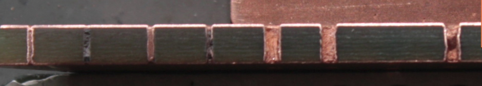
 |
| The guts of my Breakerbox: In the lower row you can see the main breaker on the left and the breakers for the stove and the water heater. |
But I also didn’t really want to mess with my breakerbox if there was any way I could avoid it. So the first things I had a look at were inductive sensors. Only two problems with that:
First, the coil or the ferrite core of the sensor has to go around the conductor you want to measure. So either the coil, the core or the conductor has to be split open to mount it. There are sensors made especially for this purpose, like these: https://www.flukso.net/content/50amp-current-clamp, so this issue could be addressed by simply throwing money at it, because those specialized sensors anren’t too cheap. Actually there are even some DIY projects for these sensors out there.
The second problem is, that these sensors only measure current. We want to measure power consumption and power is the product of current and voltage. So we’d need to measure the voltage, too, if we want accurate measurements. Now this definitely isn’t achievable without a physical connection to the conductor.
So there you have it: No accurate measurement without physical contact to hot wires. Just no way around it. Shit.
This meant, I couldn’t do his by myself. Luckily that’s not that much of a problem, because a friend of mine, who is a certified electrician, had offered to help me out.
The inevitable disclaimer:
Working with AC mains power can kill you! Don’t do it unless you really know what you’re doing!
The meter(s):
This is why some folks in Germany started the volkszaehler.org (which roughly translates to “peoples power meter”) project. This project is a really great starting point for everything about DIY smart metering. They’ve got open source software to track the consumption (among other things like temperatures) and several controller designs to connect your meters to the internet (or LAN).
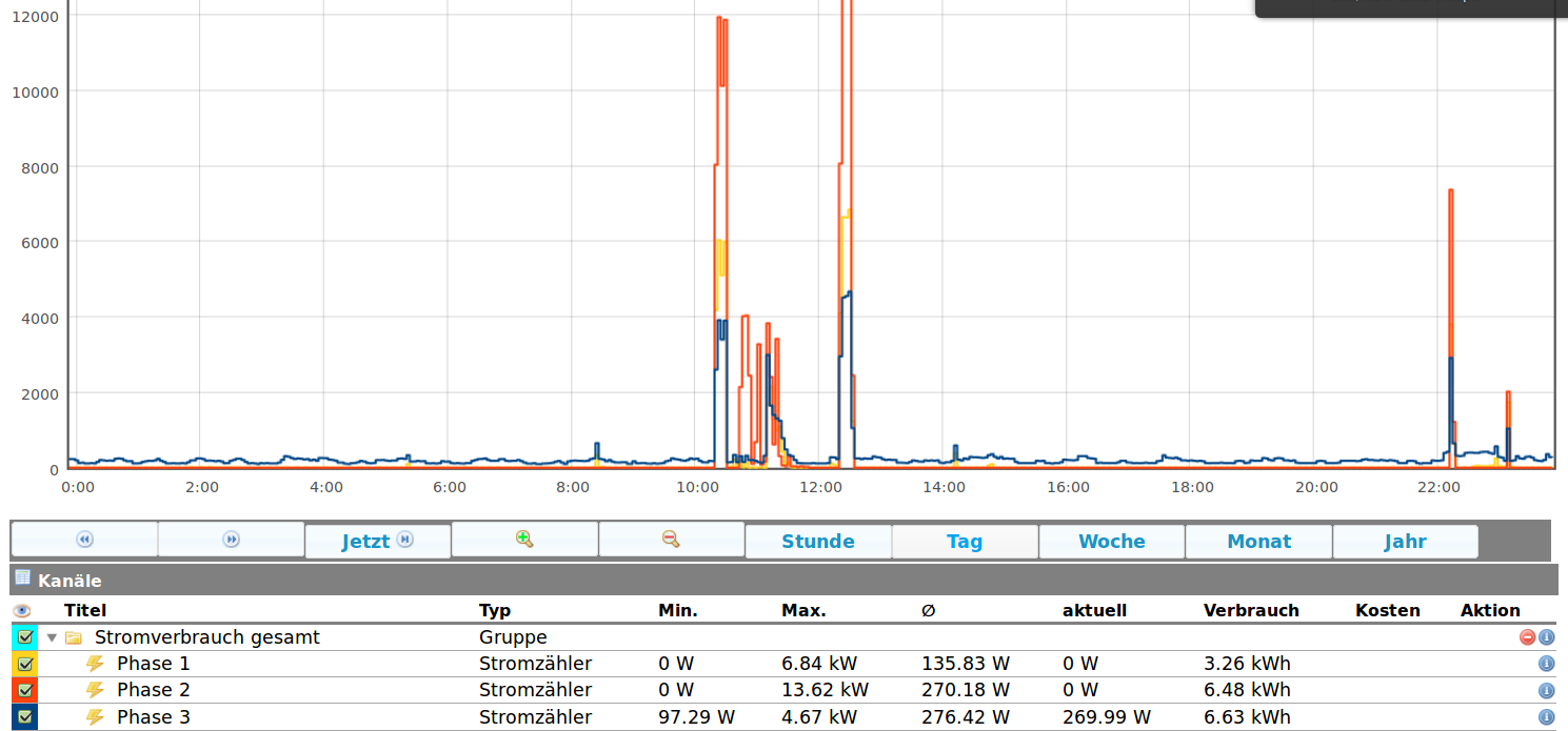 |
| This is the volkszaehler.org frontend. |
Actually I only used the power supply and the input driver boards of the project, because the controller board would be connected by Ethernet and I don’t have Ethernet anywhere near my breaker box.
There is another controller design by the same guy that uses Wifi and is compatible to the one I was building, so I tried to use that. That might have even worked had I not tried to make the PCB myself (The guy who designed these controllers also sells kits, but he had no pcb for the wifi-controller):
I have access to a little CNC-Mill capable of making PCBs via isolation routing. This is good for single sided boards (even with SMT parts like TQFPs), but it really sucks to make a double sided board on it. Especially if the board is designed to be made in a real fabrication house where they can make chemical vias, apply soldermask, and so on. The fact that I hadn’t really worked with PCB design software like eagle before, didn’t help.
So I just imported the design into eagle and didn’t care about re-positioning the vias, so that they aren’t below any parts, and milled away… That left me with a semi-functional board where everything would work fine for a while, and then the Wifi-module would perform an unprovoked factory reset.
 |
||
This was the first design. It was based on a RN171-Wifi-module and an ATTiny2313, and didn’t work. Notice how crammed the area above and on the right of the RN171 is. That’s not only capacitors and resistors, there’s a good deal of vias in there, too.
|

I spent literally months of debugging before I finally decided to can it and start from scratch.
This is what I came up with:
 |
| Not much to it. The crucial parts are an ATMega, the RFM12, and the headers to connect to the other board. |
Actually this design is derived from the JeeNode, which is (kind of) an Arduino clone with a RFM12B 868MHz FSK transceiver.
Since I was eager to keep things simple this time, and also because this was my first attempt to design a pcb in eagle (or any pcb-layout-software, for that matter), I went with a single sided board. For this all SMT-parts have to be mirrored and placed on the back. But after that epic failure with the first board I also decided to use as few SMT-parts as possible. Luckily the RFM12B is the only one and that’s also comfortably big.
 |
| The layout in eagle. Notice the RFM12B on the back of the board |
Before you can feed the layout to the router, you have to convert the eagle file to gcode, and while you’re at it, you could just widen the traces a bit, so that you’d have a bit less milling. If you don’t know what I’m talking about, the next few pictures are pretty self-explanatory.
 |
| This is what the layout looks like before being “blown up” |
 |
| This is what the layout looks like after the traces have been “blown up”. The colors are added by the software to ease identifying traces and nets. |
 |
| The milled and drilled board. I only remembered to take a picture after I already had started soldering stuff to it. Note that it’s no problem to route traces between IC-pins. Also note that some holes (e.g. the ones for the pin headers) are wider than others. |
This was done with pcb2gcode which is available at http://sourceforge.net/apps/mediawiki/pcb2gcode/index.php?title=Main_Page.
Unfortunately, there aren’t any more photos of the construction because I broke my phone’s camera function.
The receiver:
– Tell me, Captain Obvious, what good is a single RFM12B radio transceiver if it has no one to talk to?
– Well, not too much, obviously!
Anything with a RFM12B module (and probably others) can act as a receiver for the power meter.
I went and built a receiver into my Asus WL500gP Wifi-router, but you don’t have to:
There are (Arduino compatible) kits and assembled USB-dongles that contain a RFM12B and an ATMega328 available at http://jeelabs.com/, so you could just get a JeeLink or a JeeNode USB and use that.
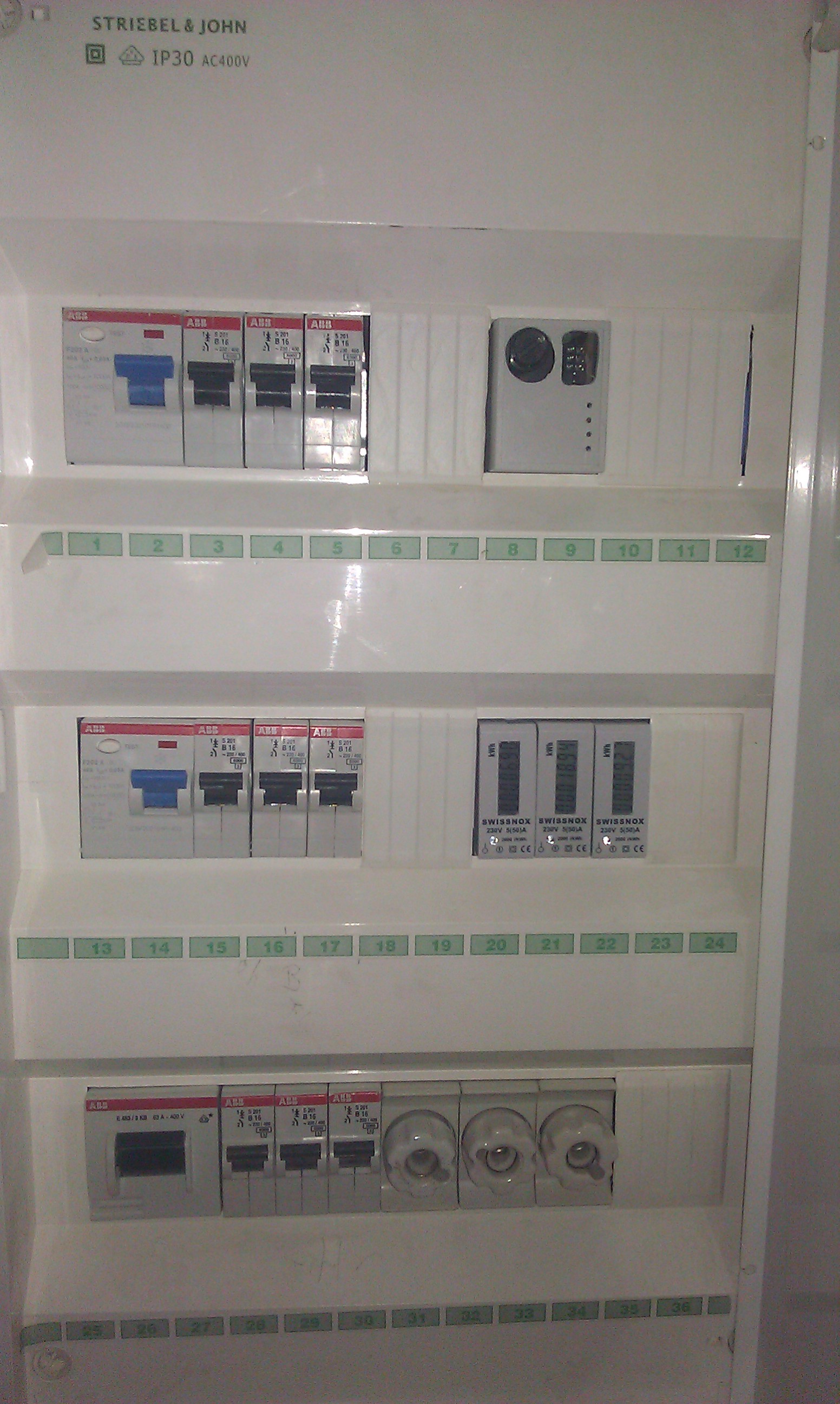 |
| My breakerbox with my smartmeter in it: Upper row: The controller, middle row on the right: The three meters. |